Do you have a question about the Pioneer PDP-503PE and is the answer not in the manual?
Lists accessories included with the product.
Product contains lead and chemicals known to cause cancer or birth defects.
Fuse symbols on PCB indicate replacement parts must be identical.
General safety precautions to be observed during servicing.
Identifies areas where commercial AC power is used without transformer.
Identifies areas with voltage 100V or more, posing shock risk.
Conform to regulations and follow safety instructions during servicing.
Essential for maintaining original product performance and specifications.
Details on packing parts and their identification numbers.
Compares parts specific to PDP-503PE/WYVI6 and PDP-503PU/KUC models.
Lists parts for the first under layer section with their respective part numbers.
Lists parts for the second under layer section with their respective part numbers.
Lists parts for the third under layer section with their respective part numbers.
Lists parts for the fourth under layer section with their respective part numbers.
Lists parts for the fifth under layer section with their respective part numbers.
Lists parts for the first middle layer section with their respective part numbers.
Lists parts for the second middle layer section with their respective part numbers.
Instructions for setting slide switches when replacing the MR INTERFACE Assy.
Lists parts for the first upper layer section with their respective part numbers.
Lists parts for the second upper layer section with their respective part numbers.
Compares parts specific to PDP-503PE/WYVI6 and PDP-503PU/KUC models.
Lists parts for the front case section with their respective part numbers.
Compares parts specific to PDP-503PE/WYVI6 and PDP-503PU/KUC models.
Lists parts for the rear section with their respective part numbers.
Compares parts specific to PDP-503PE/WYVI6 and PDP-503PU/KUC models.
Lists components that make up the PDP Service Assy 503.
Lists components that make up the Panel Chassis (50) Assy.
Lists assemblies related to the Panel Chassis (50) Assy.
Overview block diagram of the system's functional units.
Detailed overall block diagram illustrating signal flow and connections.
Pin voltage information for the MDR connector.
Pin voltage information for the 50P_FFC connector.
Pin voltage information for the 50P_FFC connector.
Pin voltage information for the DVI connector.
Block diagram and voltage measurements for the Audio Amp Assy.
Block diagram for the Speaker Terminal Assy.
Oscilloscope waveforms for the Digital Video Assy signals.
Conditions and settings for audio measurements.
Warnings regarding connecting measurement instruments to the audio amplifier.
A list of major assemblies with their part numbers.
Parts list for the Scan (A) Assy, categorized by component type.
Parts list for the Scan (B) Assy, categorized by component type.
Parts list for the X Drive Assy's logic block.
Parts list for the X Drive Assy's SUS block.
Parts list for the Y Drive Assy's logic block.
Parts list for the Y Drive Assy's SUS block.
Parts list for the Digital Video Assy's interface block.
Parts list for the Digital Video Assy's panel UCOM block.
Parts list for the Digital Video Assy's module UCOM block.
Parts list for the Digital Video Assy's digital block.
Parts list for the MR Interface Assy's interface block.
Explains how to enter and operate the service factory mode.
Details the remote control keys used for adjustments.
Notes on adjustments for the Y Drive Assy after repair or replacement.
Notes on adjustments for the X Drive Assy after repair or replacement.
Procedures for adjusting VOFS, VH, and IC5V voltages.
Details on using RS-232C commands for panel control.
Setup for connecting the PC to the plasma display via RS-232C.
Specifies the fixed communication baud rate.
Details of GAJ command output data.
Details of GPW command output data.
Information related to diagnosing issues with the plasma display.
Diagram showing the location of PCBs on the rear view.
Details on shut down diagnosis and how to release it.
Details on power down diagnosis and how to release it.
Diagnosis for panel microcomputer communication failure.
Diagnosis for DIGITAL-IIC communication failure.
Diagnosis for dew drop detection abnormalities.
Diagnosis for temperature abnormalities.
Function and usage of the large-signal system power switch.
Function and setting of the 200V AC power-down switch.
Explanation of VOFS voltage temperature compensation.
Instructions and precautions when a fuse blows.
Information on panel drive voltage adjustment.
Information about the detect switch system.
General precautions and guidelines for disassembly.
Steps for removing the SW Power Supply Module.
Lists common ICs used in the unit.
Pin assignment for SN755860PJ in Scan B Assy.
Pin assignment for SN755860PJ in Scan A Assy.
General information about Scan ICs.
Pinout and function for the panel microcomputer.
Details the function of each pin on the Panel Microcomputer.
Pin assignment diagram for IC3003.
Block diagram for IC3003.
Pin assignment diagram for IC2006.
Block diagram for IC2006.
Pin assignment diagram for IC1208.
Block diagram for IC1208.
Details the function of each pin on IC1208.
Pin assignment diagram for IC1802.
Block diagram for IC1802.
Details the function of each pin on IC1802.
Block diagram of the PDP Pulse Module IC.
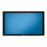
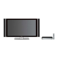
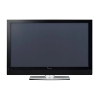
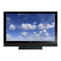
Overview of the plasma display's front panel features.
| Display Type | Plasma |
|---|---|
| Screen Size | 50 inches |
| Brightness | 1000 cd/m² |
| Response Time | 0.001 ms |
| Aspect Ratio | 16:9 |
| Viewing Angle | 160° |
| Input Ports | Component, Composite, S-Video |







 Loading...