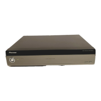
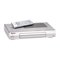
This document provides service information for the Pioneer Media Receiver, model PDP-R05G.
Function Description
The Pioneer Media Receiver PDP-R05G is designed to work in conjunction with Pioneer Plasma Displays, specifically the PDP-505PG or PDP-435PG, for adjustment and operation inspection. It acts as a central hub for various audio and video signals, processing them for display on a plasma screen. The device supports multiple color systems and TV functions, including various receiving systems, tuner bands, and auto channel presets. It also features a range of input and output terminals for comprehensive connectivity.
Important Technical Specifications
General:
- Model: Media Receiver, PDP-R05G
- Power Requirement: 110-240 V ~, 50/60 Hz, 35 W (0.4 W Standby)
- Dimensions (W x H x D): 420 x 90 x 295 mm
- Weight: 4.9 kg
- Design and specifications: Subject to change without notice.
TV Function:
- Color System: PAL/SECAM/NTSC/4.43 NTSC//PAL-M/PAL-N
- Receiving System: PAL (B/G, D/K, I, M, N), SECAM (B/G, D/K), NTSC (M, 4.43NTSC, M)
- Tuner: VHF/UHF (44.25-863.25 MHz), CATV (Hyper-band, S1–S41ch)
- Auto Channel Preset: 99 ch (Normal), 68 ch (Air, US type), 125 ch (Cable, US type), Auto Preset
- Audio Multiplex: NICAM/A2/BTSC System
Terminals:
- Rear Inputs:
- INPUT 1: Component Video in, S-Video in, AV in
- INPUT 2: S-Video in, AV in
- INPUT 3: Component Video in, S-Video in, AV in, HDMI in
- Antenna: 75 Ω Din Type for VHF/UHF in
- Front Inputs:
- INPUT 4: S-Video, AV in
- PC: 15 Pin mini D-Sub, Audio in
- Rear Outputs:
- MONITOR OUTPUT Terminal: S-Video out, AV out
Included Accessories:
- Remote control unit (AXD1492)
- System cable (3 m) (ADF1026)
- Stand (AXG1013)
- AA size battery x 2 (Manganese battery) (VEM1031)
- Screw x 4 (PMB40P120FZK) (for stand)
- Screw hole cap x 4 (AMR3363)
- Operating instructions
Internal Components (Key ICs and Modules):
The device incorporates several key integrated circuits and modules for signal processing, control, and memory functions. These include:
- MR Main Board Assy (AWV2157): Contains the core processing units, including AD9883AKST-110 (Analog Interface), SM5301BS (Video Filter), BA7078AF (Multimedia IC), Sil9993CTG100 (HDCP Panel Link Receiver), HY57V643220CT-7 (Synchronous DRAM), MBM29PL3200BE70PFV (Flash Memory), Sil170BCLG64 (HDCP Panel Link Transmitter), and various other logic ICs and microcontrollers (e.g., MB91F355APMTGE1 Main UCOM).
- AV Board Assy (AWZ6982): Includes the TV Tuner (AXF1119, U7501), Multisound Processor (MSP3455G, IC7502), 7-Input 3-Output Audio/Video Switch (CXA2069Q, IC8002), RGB to YUV/IQ High-speed Matrix IC (TA1287FG, IC8906), and Teletext Decoder (SDA6000, IC8904).
- MDR Assy (AWZ6778): Contains components for audio and control signals.
- SR Assy (AWZ6817): Includes components for serial communication.
- Front Assy (AWZ6975): Houses the sensor block and front panel controls.
- LED Assy (AWZ6816): Manages LED indicators.
- REG Assy (AWZ6833): Contains DC-DC converter units (AXY1066, U8502).
- Power Supply Unit (AXY1093): Provides power to all components.
Usage Features
The Media Receiver is designed for seamless integration with Pioneer Plasma Displays. It offers a wide array of connectivity options for various audio and video sources, including component video, S-video, AV, HDMI, and PC inputs. The front panel provides convenient access to INPUT 4 (S-Video, AV in) and PC input. The remote control unit (AXD1492) is the primary interface for operating the device, especially in Service Factory mode.
Service Factory Mode:
This mode allows technicians to perform adjustments and diagnostics.
- Access: Use the supplied remote control unit.
- Functions: Includes information display (version, serial, panel power-down/shutdown logs, temperature, hour meters, pulse meter, P ON counter, digital EEPROM status, HDMI signal info, tuner signal info), function checks (IC tests, FAN control, AFT lock, BSD ANT VOLT, AUTO PRESET CHECK), individual adjustments (CVY/RY/GY/BY GAIN), common adjustments (RGB 1/2, PANEL 1/2), option settings (pattern mask, full mask, peak limiter, dynamic range, EDID write mode, EU CH preset), and initialization settings (sync det, drive mode, side mask level, panel revice, final setup, C temp settings, BSD factory, UART select, CVT auto).
- RS-232C Control: The device supports RS-232C commands for external control and diagnostics. It can be switched between SR+ and RS-232C control modes.
- TRAP Switch: A detection switch is included to prevent panel technology leakage if the upper plate is accidentally opened. This switch is disabled when the unit is turned off. For internal diagnosis, it can be fixed to the OFF position using adhesive tape.
Maintenance Features
This service manual is intended for qualified service technicians. It emphasizes safety precautions and proper repair procedures.
Safety Precautions:
- Qualified Technicians: Repairs should only be performed by qualified service technicians with necessary test equipment and tools.
- Lead in Solder: The product contains lead in solder and certain electrical parts contain chemicals known to cause cancer, birth defects, or other reproductive harm (Proposition 65).
- Leakage Current Check: A leakage current check must be performed after repairs, ensuring current does not exceed 0.5 mA to a known earth ground.
- Product Safety Notice: Many parts have special safety-related characteristics, identified by a "!" mark in schematics and parts lists. Replacements must be identical to PIONEER recommended parts to avoid shock, fire, or other hazards.
Important Check Points for Good Servicing:
- Product Safety: Conform to product regulations and maintain a safe servicing environment.
- Parts Usage: Use specified, genuine parts for repair, especially for safety-critical components.
- Modifications: Do not perform modifications without proper instructions.
- Soldering: Ensure proper soldering without cold solder or debris.
- Fasteners: All screws must be tightly fastened.
- Connectors: All connectors must be correctly inserted.
- Cables: Wiring cables should be in their original state, without pinched wires.
- Internal Debris: No screws or solder debris should remain inside the product.
- Power Cord: Check for semi-broken wires, scratches, or melting. Replace damaged power cords.
- Power Plug: Check for spark traces and ensure secure connections.
- Environment: Pay attention to static electricity, furniture, and household articles during repairs.
Adjustments:
- Purpose: To restore original performance, optimum adjustments, and characteristic confirmation.
- Procedure: Follow the procedures described in the manual.
- Memory: Values changed in Service/Factory mode are stored in memory. Note original values before readjustment.
- Power Supply: Use a stable AC power supply.
- Readjustment Cases: Readjustment is generally not required if an assembly is replaced, except for the AV Board Assy if the front end is replaced.
- Adjustment Items: AFC Adjustment, RF-AGC Adjustment, Video Level Adjustment.
Cleaning:
- Purpose: Restore performance for parts requiring cleaning (optical pickups, tape deck heads, lenses, mirrors).
- Tools: Use prescribed cleaning tools, e.g., cleaning paper (GED-008) for fans.
Shipping Mode and Screws:
- Purpose: Protect products from damage during transit.
- Procedure: Set shipping mode or install shipping screws as specified in the manual.
Troubleshooting:
- Flowcharts: Detailed flowcharts are provided for troubleshooting common issues like "Image for the composite or S signal is not displayed," "Image for the component or RGB signals is not displayed," and "No sound."
- Waveforms and Voltages: Reference waveforms and voltage values are provided for various test points and IC pins to aid in diagnosis.
- LED Lighting Patterns: The manual describes LED lighting patterns to indicate the status of the unit (standby, power on, power not on, system cable disconnected, microcomputer rewriting, shutdown, TRAP switch operation) and to diagnose defective points.
Parts List:
- Comprehensive lists of assemblies, semiconductors, coils, filters, capacitors, resistors, and other parts are provided, with part numbers and descriptions. Safety-critical parts are marked.