EasyManua.ls Logo

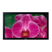
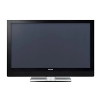
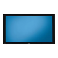
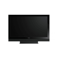
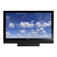
Pioneer PRO-507PU

Pioneer PRO-507PU
39 pages
To Next Page IconTo Next Page
Loading...
ORDER NO.
PIONEER CORPORATION 4-1, Meguro 1-chome, Meguro-ku, Tokyo 153-8654, Japan
PIONEER ELECTRONICS (USA) INC. P.O. Box 1760, Long Beach, CA 90801-1760, U.S.A.
PIONEER EUROPE NV Haven 1087, Keetberglaan 1, 9120 Melsele, Belgium
PIONEER ELECTRONICS ASIACENTRE PTE. LTD. 253 Alexandra Road, #04-01, Singapore 159936
PIONEER CORPORATION 2006
ARP3399
T – ZZY SEPT. 2006 Printed in Japan
THIS MANUAL IS APPLICABLE TO THE FOLLOWING MODEL(S) AND TYPE(S).
Model Type Power Requirement
Remarks
PRO-507PU KUCXC AC120 V
PRO-507PU
PLASMA DISPLAY
This service manual should be used together with the following manual(s):
Model No. Order No. Remarks
PDP-5071PU/KUCXC ARP3354 SAFETY INFORMATION, EXPLODED VIEWS AND PARTS LIST, BLOCK DIAGRAM,
PCB PARTS LIST, ADJUSTMENT, IC INFORMATION etc.
ARP3355 SCHEMATIC DIAGRAM and PCB CONNECTION DIAGRAM
CONTENTS
1. CONTRAST OF MISCELLANEOUS PARTS .............................. 2
2. BLOCK DIAGRAM AND SCHEMATIC DIAGRAM ................... 10
2.1 OVERALL WIRING DIAGRAM............................................ 10
2.2 HNM BLOCK DIAGRAM ..................................................... 12
2.3 CONNECTOR PIN DESCRIPTION .................................... 13
2.4 HN MODULE ASSY (1/6) .................................................... 14
2.5 HN MODULE ASSY (2/6) .................................................... 18
2.6 HN MODULE ASSY (3/6) .................................................... 20
2.7 HN MODULE ASSY (4/6) .................................................... 22
2.8 HN MODULE ASSY (5/6) .................................................... 24
2.9 HN MODULE ASSY (6/6) .................................................... 26
3. PCB CONNECTION DIAGRAM ................................................ 28
3.1 HN MODULE ASSY ............................................................ 28
4. TROUBLESHOOTING .............................................................. 30
5. IC INFORMATION..................................................................... 33
Question and Answer IconNeed help?

Do you have a question about the Pioneer PRO-507PU and is the answer not in the manual?

Pioneer PRO-507PU Specifications

General IconGeneral
Screen Size50 inches
Display TypePlasma
Aspect Ratio16:9
Brightness1100 cd/m²
Contrast Ratio3000:1
Viewing Angle160°
Input PortsComponent, Composite, S-Video

Summary

Service Manual Overview

Applicable Models and Types

Details models and types this service manual applies to.

Related Service Manuals

Lists other manuals recommended for use with this service manual.

Miscellaneous Parts Information

Packing Section Details

Provides information and diagrams for the packing section.

Packing Parts List

Exterior Section Contrast

PCB Assemblies Contrast

Compares differences in PCB assemblies between models.

Front and Rear Section Contrast

Compares differences in front and rear sections between models.

Exploded Views of Components

HOME NETWORK MODULE Replacement Guide

PCB Assemblies Contrast: Main Assy

Component Contrast: Tanshi, Pod, Side, HN Assys

Component Details: Various Blocks

Block and Schematic Diagrams

Overall Wiring Diagram

Illustrates the overall wiring connections between major units.

Connector Pin Assignments

HNM Assembly Block Diagram

Connector Pin Descriptions

HN Module Assembly Schematics (Part 1)

HN Module Assembly Schematics (Part 2)

HN Module Assembly Schematics (Part 3)

HN Module Assembly Schematics (Part 4)

HN Module Assembly Schematics (Part 5)

HN Module Assembly Schematics (Part 6)

PCB Connection Diagrams

HN Module Assembly Connections

Shows PCB component layout and connections for the HN Module.

HN Module Assembly Component Layout (Side B)

Troubleshooting Guide

Network Operation Failures

Troubleshooting steps for problems with network media playback.

Troubleshooting: USB Operation

Troubleshooting: Fundamental Operation

IC Information

RTL8100 CL-LF Ethernet Controller

Details the RTL8100CL-LF Ethernet Controller IC and its pinout.

Block Diagram of RTL8100 CL-LF

Pin Descriptions

Power ManagementIsolation Interface

Describes pins related to power management and bus isolation.

PCI Interface Pin Details

Interface and Power Pins

EPROMEEPROM InterfaceAUX

Details the interface for EPROM/EEPROM and auxiliary functions.

Power Pins

Lists all power supply pins and their types.

LED Interface

Describes the signals controlling the unit's LEDs.

Attachment and Test Pins

Attachment Unit Interface

Details the interface for attachment units.

Test and Other Pins

Describes test points and miscellaneous pins.

Related product manuals