Do you have a question about the Pioneer KRP-500P and is the answer not in the manual?
Warning about chemicals in electrical parts causing cancer/birth defects.
General safety precautions to be observed during service and handling.
Conforming to regulations and maintaining a safe servicing environment.
Recommended items to check to ensure product quality after repair work.
Information on power supply operation status indicated by LEDs.
Details the sequence of operations when the unit powers on, including signal flow.
Comprehensive breakdown of the power-on sequence under different operating modes.
Procedures for diagnosing and analyzing system failures.
Flowchart for analyzing and diagnosing failures within the power supply unit.
Flowcharts for diagnosing failures in the Drive Assy, including panel connections and signal integrity.
Flowcharts for diagnosing failures in the Digital Assy, checking input signals and connections.
Flowcharts for diagnosing failures in the Main Assy, focusing on power and interface functions.
Flowchart for diagnosing audio system failures, checking sound output and signals.
Block diagram illustrating the power-down signal flow and detection points.
Block diagram illustrating the shutdown signal flow and detection points.
Details the panel drive-power ON/OFF function for circuit operation without panel power.
Flowchart for diagnosing failures of the entire unit based on LED indicators.
Troubleshooting steps for power-on states and LED indications.
Troubleshooting steps for power-down (PD) and shutdown (SD) related issues.
Troubleshooting steps for video display anomalies and abnormal screen conditions.
Troubleshooting steps for audio output and speaker problems.
Step-by-step guide to diagnose power supply unit failures based on voltage and component checks.
Step-by-step guide to diagnose drive Assy failures based on waveform and connection checks.
Step-by-step guide to diagnose digital Assy failures based on signal input and connector checks.
Step-by-step guide to diagnose Main Assy failures related to power, remote control, and video signals.
Step-by-step guide to diagnose audio system failures based on sound output, muting, and signal checks.
Diagram showing how power-down signals are detected across different assemblies.
Table detailing PD failure analysis based on LED flashing count, defective Assy, and checkpoints.
Diagram showing how shutdown signals are detected across different assemblies.
Table detailing SD failure diagnosis based on LED flashing frequency, type, and factory mode logs.
Detailed information on the factory menu structure and available functions for panel adjustment.
Identifies assemblies requiring adjustment or backup data transfer after replacement.
Procedures for backing up and copying EEPROM data for the DIGITAL Assy.
Procedures for adjusting the unit after replacing the service panel assembly.
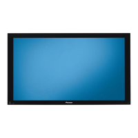
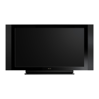
| Screen Size | 50 inches |
|---|---|
| Panel Type | Plasma |
| HDMI Ports | 3 |
| Component Video Inputs | 2 |
| Resolution | 1920 x 1080 |
| Input Ports | HDMI, Component, Composite, S-Video |






 Loading...