109
KRP-500P
5
6 7 8
5
6 7 8
A
B
C
D
E
F
7. DISASSEMBLY
7.1 FLOWCHART OF REMOVAL ORDER
1
Under grip
LS (50F)
1
Rear case
(509M)
2
Under cover
(509M)
2
Terminal panel
SEP
5
Front chassis
HT Assy 509
3
Multi base Assy
SEP
4
F-case Assy
(500SEP)
SENSOR
5
Front chassis
HB Assy 509
5
Address plate
S, L (509)
5
Sub frame L Assy
(509)
5
Sub frame R Assy
(509)
SENS FAN
1
Under grip
R (50F)
POW SW
MAIN AUDIO
50F DIGITAL
6
Front chassis
V (509M)
LED RLS
50F SCAN A 50F SCAN B
IR
POWER
SUPPLY
50F X DRIVEFAN CH 50F Y DRIVE
50F
ADDRESS S
50F
ADDRESS L
It is efficient to proceed with removal of the main parts and boards in the order shown in the chart below:
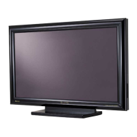
Note: Even if the unit shown in the photos and illustrations in this manual may differ from your product, the procedures
described here are common.
Flowchart of removal order for the main parts and boards
NOTE ∗1: When replacing the X DRIVE Assy or Y DRIVE Assy, check the silicon
sheet is on the new service part or panel chassis.
∗1 ∗1

 Loading...
