EasyManua.ls Logo

Pioneer SA-1490 User Manual

Pioneer SA-1490
20 pages
To Next Page IconTo Next Page
Page #1 background imageLoading...
Page #1 background image
Operating
Instructions
QPIONEER
stesco
cram
squaczes
STEREO
AMPLIFIER
A-149S0
SD,
SD/G
Thank
you
for
buying
this
Pioneer
product.
Please
read
through
these
operating
instructions
so
you
will
know
how
to
operate
your
model
properly.
After
you
have
finished
read-
ing
the
instructions,
put
them
away
in
a
safe
place
for
future
refer-
ence.
FM/AM
DIGITAL
SYNTHESIZER
TUNER
X=-109S0
In
some
countries
or
regions,
the
shape
of
the
power
plug
and
power
outlet
may
sometimes
differ
from
that
shown
in
the
explan-
atory
drawings.
However,
the
method
of
connecting
and
operating
the
unit
is
the
same.
See
pp.
13-19.
WARNING:
to
prevent
FIRE
OR
SHOCK
HAZARD,
DO
NOT
EXPOSE
THIS
APPLIANCE
TO
RAIN
OR
MOISTURE.
IMPORTANT
NOTICE
{For
U.S.
and
Canadian
models]
The
serial
number
for
this
equipment
is
located
on
the
rear
panel.
Please
write
this
serial
number
on
your
enclosed
war-
ranty
card
and
keep
it
in
a
secure
area.
This
is
for
your
securi-
ty.
[For
Canadian
model]
CAUTION:
to
prevent
ELECTRIC
SHOCK
DO
NOT
USE
THIS
(POLARIZED)
PLUG
WITH
AN
EXTENSION
CORD,
RECEPTACLE
OR
OTHER
OUTLET
UNLESS
THE
BLADES
CAN
BE
FULLY
INSERTED
TO
PREVENT
BLADE
EXPOSURE.
ATTENTION:
pour
prevenir
LES
CHOCS
ELEC-
TRIQUES
NE
PAS
UTILISER
CETTE
FICHE
POLARISEE
AVEC
UN
PROLONGATEUR
UNE
PRISE
DE
COURANT
OU
UNE
AUTRE
SORTIE
DE
COURANT,
SAUF
SI
LES
LAMES
PEUVENT
ETRE
INSEREES
A
FOND
SANS
EN
LAISSER
AUCUNE
PARTIE
A
DECOUVERT.
LINE
VOLTAGE
SELECTOR
SWITCHES
Only
multi-voltage
models
are
provided
with
these
switches,
U.S.A.,
Canadian,
U.K.,
Australia
and
Europe
models
are
not
provided
with
them.
Mains
voltages
in
Saudi
Arabia
are
127V
and
220V
only.
Never
use
this
model
set
to
110V
in
Saudi
Arabia
You
will
find
the
line
voltage
selector
switches
on
the
rear
panel.
Before
your
model
is
shipped
from
the
factory,
the
switches
are
set
to
the
power
requirements
of
the
destina-
tion;
nevertheless,
you
should
check
that
they
are
set
prop-
erly
before
plugging
the
power
cord
into
the
wall
custiet.
If
the
voltage
requirements
differ,
adjust
the
selector
switches
as
follows.
Before
adjusting,
disconnect
the
power
cord.
1.
Use
a
medium-size
screwdriver:
2.
Insert
the
screwdriver
into
the
groove
on
the
voltage
selec-
tor,
and
adjust
so
that
the
tip
of
the
arrow
point;
to
the
voltage
value
of
your
area.
PN
Set
the
voltage
selector
for
the
voltage
in
your
area.
2)
avin
CoN
e
7
VOLTAGE
SELETRON
Medium-sreé
WOv
127V
20V-
m0v
screwdrivir
Q)
PIONEER’
The
future
of
sound
and
vision.
3
Question and Answer IconNeed help?

Do you have a question about the Pioneer SA-1490 and is the answer not in the manual?

Pioneer SA-1490 Specifications

General IconGeneral
Signal-to-Noise Ratio90 dB
Input sensitivity150 mV
Frequency Response10 Hz - 50 kHz
Dimensions420 x 145 x 330 mm (W x H x D)
Output150mV (line)
Speaker load impedance4Ω to 16Ω

Summary

Line Voltage Selector Switches

Voltage Selector Switch Operation

Details on adjusting line voltage selector switches for correct power input.

Safety Precautions for Voltage Selection

Important safety notes regarding power cord disconnection before adjustment.

Safety Instructions

General Safety Guidelines

Core instructions for safe operation, retention, warnings, and following guidance.

Installation and Environmental Safety

Guidelines on placement, ventilation, heat, power sources, and cleaning.

Power Cord and Polarization Safety

Instructions for power cord protection and proper use of polarized plugs.

Outdoor Antenna Grounding

Recommendations for grounding outdoor antennas for protection and noise reduction.

Product Features

Amplifier Specifications and Capabilities

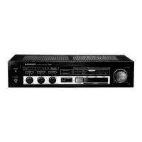
Details on high power output, remote control, equalizer, and sleep timer functions.

Before Using This Component

Accessory Check

Ensuring all necessary accessories, like remote control and batteries, are present.

Connecting Components

Audio Source Connections

Connecting VDP, CD player, Tape deck, and adaptor components for audio input.

Remote Control and Inter-Component Connections

Connecting the REMOTE CONTROL OUT jack for system control.

Speaker Wire Connections

Speaker Impedance Guidelines

Control Signal Connections

Power Cord Connections

Names and Uses of Parts

Front Panel Controls Overview

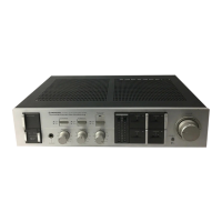
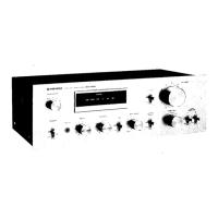
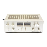
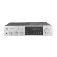
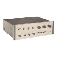
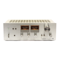
Descriptions of power switch, headphone jack, speaker switches, sensor window, function switches, power indicator, and balance control.

Audio Adjustment and Display Controls

System Memory and Indicator Functions

Explanation of the standby/sleep indicator and the component's memory recall feature.

Operating the Amplifier

Initial Setup and Controls

Setting the power, speaker, muting, and balance controls before operation.

Playback Procedures

Step-by-step guide for powering on, selecting sources, playing equipment, and adjusting volume/tone.

Recording Audio Tapes

Using Adaptor Components

Sound Compensation with Graphic Equalizer

Troubleshooting Amplifier Issues

Power and Sound Issues

Troubleshooting steps for no power, no sound, or sound from only one speaker.

Recording and Other Issues

Troubleshooting for tape recording problems and other common issues.

Amplifier Specifications

Tuner Features

Tuner Presets and Reception Modes

Details on 24-station presetting and FM MONO reception for clearer tuning.

Tuner Accessories

Included Tuner Accessories

List of supplied accessories: AM loop antenna and FM T-type antenna.

Tuner Connections

Antenna Installation and Grounding

Connecting FM T-type and AM loop antennas, with notes on grounding and installation.

Connecting Tuner to Amplifier

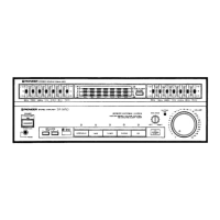
Diagram showing connection between the Tuner (TX-1090Z) and Stereo Amplifier (SA-1490).

Antenna Connection Details

FM and AM Antenna Types

Details on connecting FM T-type, AM loop, indoor, and outdoor antennas.

AM/FM Channel Step Switch

Explanation of the AM/FM channel step switch for tuning frequency increments.

Tuner Controls and Indicators

Tuner Tuning and Selection Controls

Details on FM MONO, tuning modes, station call, memory, and band selection.

Tuner Display and Indicators

Explanation of the frequency display, tuning indicators, and stereo reception indicator.

Tuner Operations

Tuning FM/AM Broadcasts

Steps for manual and auto tuning, selecting bands, and adjusting volume/tone.

Preserving Stations

Guide to presetting FM/AM stations into memory for quick recall.

Memorizing and Recalling Stations

Station Memory Retention and Last Station Recall

Information on how station presets are saved and how the last station is recalled.

Tuner Troubleshooting

Tuner Sound and Reception Issues

Troubleshooting for no sound, FM/AM sound distortion, and stereo reception problems.

Tuner Specifications

Related product manuals