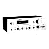
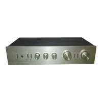
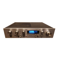
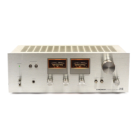
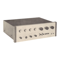
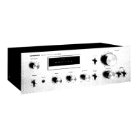
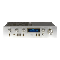
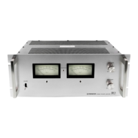
2. FRONT PANEL
FACILITIES
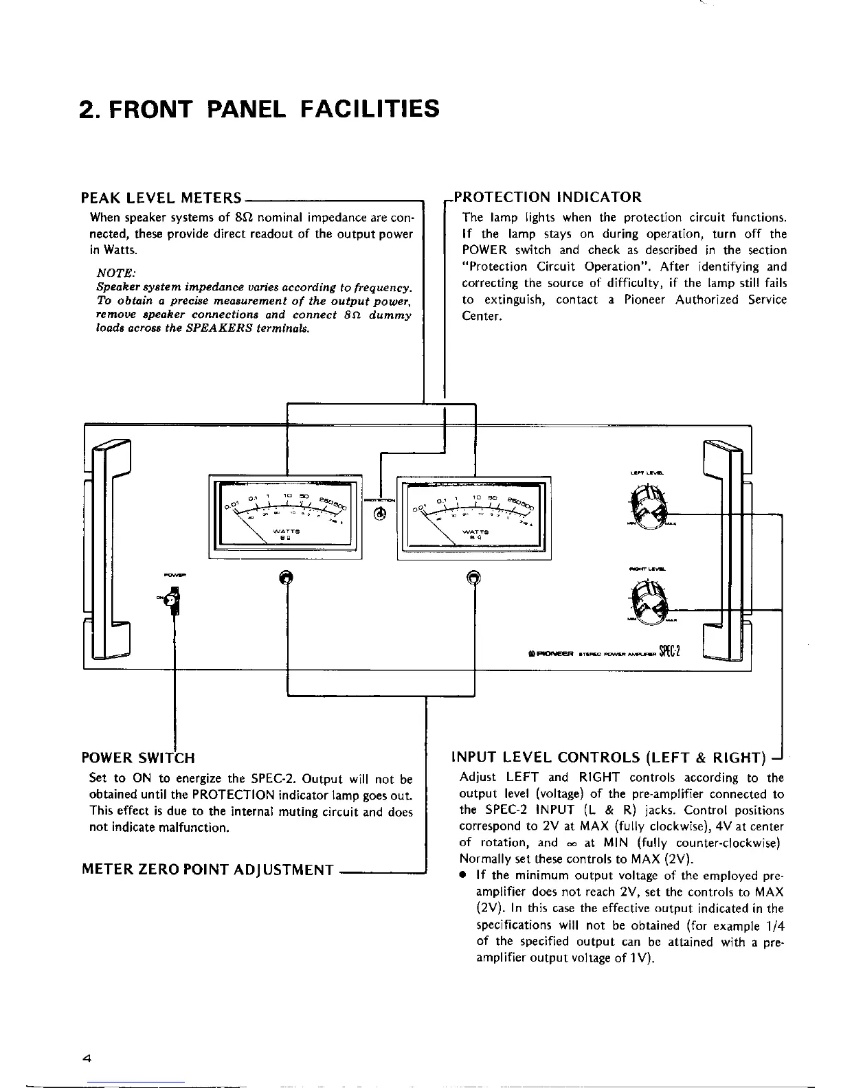
PEAK LEVEL
METERS
When
speaker
systems of 8O nominal impedance
are con-
nected, these
provide
direct readout
of the output
power
in Watts.
NOTE:
Speoher syotem impedance uaries
occording
to
frequency.
To
obtoin o
preciae
medsurcment
of the output
poue\
remoue
Spedher con\ectiotrs
ond
connect
8a dumtuy
loods ocro4i the SPEAKERS
termindls-
POWER
SWI CH
S'et to ON
to energize
the SPEC-2. Output will
not be
obtained until
the PRoTEcTIoN
indicator lamp
Soes
out.
This effect
is due to
the internal muting
circuit and does
not indicate
malfunction.
METER
ZERO POINT
ADJ USTMENT
PROTECTION INDICATOR
The
lamp lights when
the
protection
circuit functions.
lf the lamp stays
on during operation,
turn off the
POWER
switch
and check as described
in the section
"Protection
Circuit
Operation".
After identifying and
correcting the source of difficulty, if the lamp still fails
to
extinguish, contact a Pioneer
Authorized Service
Center,
INPUT
LEVEL CONTROLS
(LEFT
& RIGHT)
Adjust LEFT
and RIGHT controls according
to the
output
level
(voltage)
of the
pre-amplifier
connected to
the SPEC-2 INPUT
(L
& R)
jacks.
Control
positions
correspond to 2V
at
MAX
(fully
clockwise), 4V at center
of rotation, and d
at MIN
(fully
counter-ciockwise)
Normally
set these controls
to
MAX
(2V).
.
lf
the minimum output voltage
of the
employed
pre-
amplifier
does not reach 2V.
set the controls to MAX
(2V).
In
this case the effective output
indicated in the
specifications will
not be obtained
(for
example
1/4
of
the specified
output can
be
attained
with
a
pre-
amplifier
output voltage
of 1V).


 To Next Page