EasyManua.ls Logo

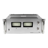
Pioneer SPEC-2 - Circuit Description; Power Amplifier Circuitry

Pioneer SPEC-2
49 pages
Print Icon
To Next Page IconTo Next Page
To Previous Page IconTo Previous Page
Loading...
4.
CIRCUIT
DESCRIPTION
4.1 POWER
AMPLIFIER
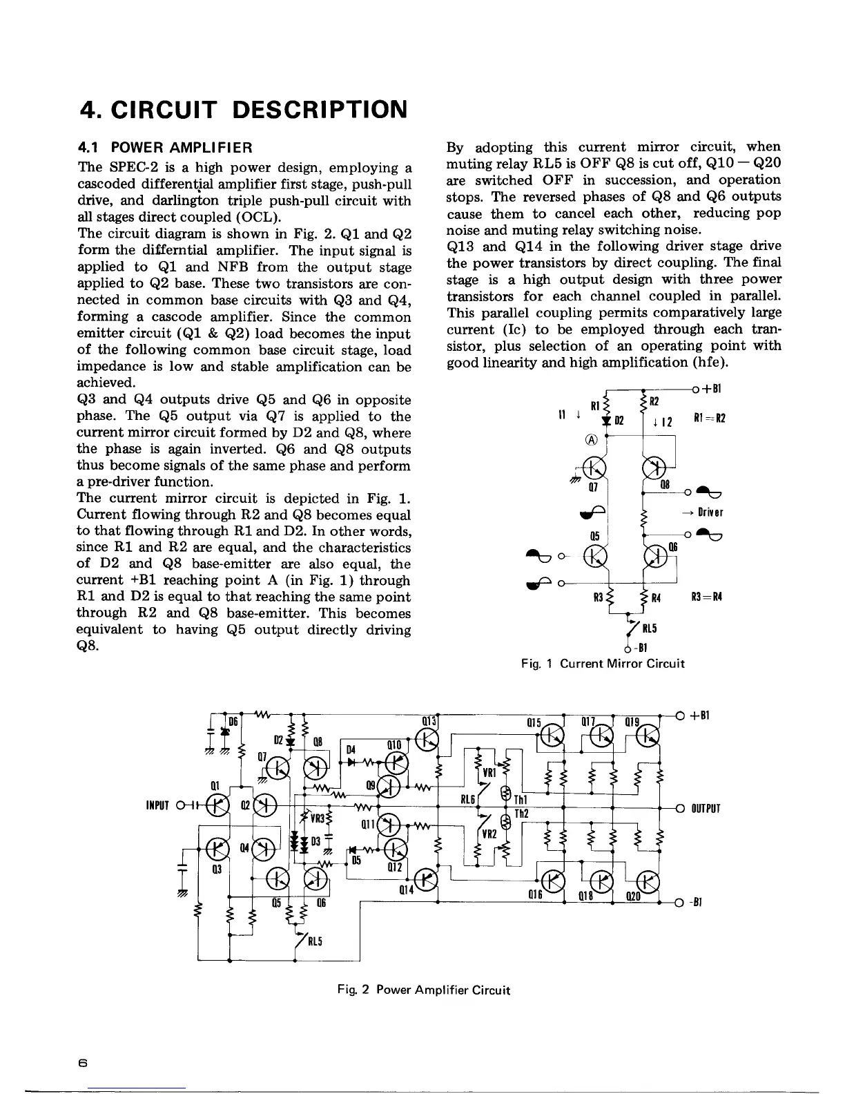
The
SPEC-2
is
a
high
power
design,
employing
a
cascoded
differential
amplifier
first stage,
push-pull
drive,
and darlington
triple
push-pull
circuit
with
all
stages
direct coupled
(OCL).
The circuit
diagram is shown
in
Fig.
2.
Q1
and
Q2
form
the
differntial
amplifier. The input
signal
is
applied
to
Q1
and
NFB
from
the output stage
applied
to
Q2
base.
These
two transistors
are con-
nected
in common base circuits
with
Q3
and
Q4,
forming
a
cascode
amplifier. Since
the common
emitter circuit
(Q1
&
Q2)
load
becomes the input
of
the following common
base circuit
stage,
load
impedance
is low
and stable
amplification can be
achieved.
Q3
and
Q4
outputs
drive
Q5
and
Q6
in opposite
phase.
The
Qb
output
via
Q7
is
applied
to the
current mirror
circuit formed
by
D2
and
Q8,
where
the
phase
is
again
inverted.
Q6
and
Q8
outputs
thus
become signals
of
the
same
phase
and
perform
a
pre-driver
function.
The
cunent
mirror circuit is
depicted
in
Fig.
1.
Current
flowing
through R2
and
Q8
becomes
equal
to
that flowing
through Rl
and
D2.
In
other words,
since
R1
and
R2
are
equal,
and the characteristics
of.
D2
and
Q8
base-emitter
are
also
equal,
the
current
+BL
reaching
point
A
(in
Fig.
1) through
R1
and
D2
is equal
to
that
reaching
the
same
point
through R2
and
Q8
base-emitter. This
becomes
equivalent
to
having
Q5
output directly
driving
Q8.
IIIPUTH
By
adopting
this
current
mirror circuit,
when
muting relay
RLb is OFF
Q8
is
cut off,
Q10
-
Q20
are
switched
OFF in succession,
and operation
stops.
The reversed
phases
of
Q8
and
Q6
outputs
cause them
to
cancel
each
other,
reducing
pop
noise
and
muting
relay switching
noise.
Q13
and
Q14
in the following
driver
stage drive
the
power
transistors
by direct coupling.
The final
stage
is
a
high
output
design
with
three
power
transistors
for
each channel
coupled
in
parallel.
This
parallel
coupling
permits
comparatively
large
current
(Ic)
to
be employed through
each
tran-
sistor,
plus
selection of an
operating
point
with
good
linearity
and
high amplification
(hfe).
+Bl
ll:t2
-
llrirel
€
Fig.
1 Current
Mirror
Circuit
tu
Fig.
2
Power
Amplifier
Circuit

Table of Contents