This document is a service manual for the Pioneer VSX-323-K AV Receiver, providing detailed information for maintenance, repair, and understanding of its internal components and functionalities. It covers various models and types, including the VSX-323-K (SYXE8, PWVXE8, and DLXE), with different power requirements to cater to various regions. The manual is intended to be used in conjunction with the HTP-072/CMXESM manual, which covers the VSX-324-K-P/YXE8, DLXE, and PWXE models, for comprehensive information on specifications and panel facilities.
Function Description:
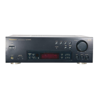
The Pioneer VSX-323-K is an AV Receiver designed to process and amplify audio and video signals, serving as the central hub for a home entertainment system. It integrates multiple functions, including audio signal processing, video signal management, power amplification for multiple channels, and various input/output options. The receiver supports both analog and digital audio inputs, as well as HDMI video inputs and outputs, allowing it to connect to a wide range of source devices such as Blu-ray players, game consoles, and set-top boxes.
The core of the receiver's audio processing capabilities includes an 8-channel volume control with input selector (IC400 R2A15218FP) and various operational amplifiers (UTC4580E, NJM41050) for signal conditioning. Digital-to-analog converters (PCM1681) and analog-to-digital converters (EPF025A) handle the conversion between analog and digital audio formats. The device features a DSP (Digital Signal Processor) for advanced audio processing and a main micom (microcontroller) for overall system control.
For video, the VSX-323-K incorporates an HDMI section with an EP9442 chip for 4-in/1-out HDMI switching, supporting video signal management. An NJM41050 video driver and an LC74781 video OSD (On-Screen Display) chip are also part of the video processing chain, enabling on-screen menus and video signal routing.
The power amplification section (AMP5 ASSY) is designed to deliver multi-channel audio output to speakers, with various transistors (e.g., 2SB1560P, 2SD2390P, 2SC3964) forming the amplification stages. The receiver includes a power transformer and a regulator board (REG ASSY) to provide stable power to all internal circuits.
Important Technical Specifications:
- Power Requirements:
- SYXE8: AC 220 V to 230 V
- PWVXE8: AC 220 V to 240 V
- DLXE: AC 110 V to 127 V/220 V to 240 V
- Audio Processing:
- 8-channel volume control with input selector (IC400 R2A15218FP)
- D/A Converter: PCM1681
- A/D Converter: EPF025A
- DSP: D808K013CPTP400
- Video Processing:
- HDMI: EP9442 (4-in/1-out)
- Video Driver: NJM41050
- Video OSD: LC74781
- Power Amplification: Multi-channel amplifier (AMP5 ASSY) with various transistors.
- Power Supply: Main transformer, STBY transformer, and regulator board (REG ASSY) with ICs like KIA7805API, KIA7812API, KIA7912PI.
- Fuses: FU301 FUSE GLASS TUBE 20MM (T3.15AL250V or T6.3AL250V depending on model).
- Crystals: X1200 CRYSTAL (14M32) for video OSD, 24.576MHZ for DSP.
- Connectors: Various terminal boards (TER, BOARD PUSH 4P, 8P, RCA 1 PIN) for audio inputs, HDMI, coaxial, optical, and speaker outputs.
Usage Features:
The VSX-323-K is designed for ease of use within a home theater setup. While specific usage features are typically detailed in the operating instructions (which this manual refers to), the block diagrams and component lists suggest a comprehensive set of functionalities:
- Multiple Inputs: The receiver supports multiple analog audio inputs (TUNER, CD, SAT, DVD), digital audio inputs (COAXIAL, OPTICAL), and HDMI inputs, allowing users to connect various source devices.
- Multi-channel Audio Output: It provides multi-channel speaker outputs (FL, FR, C, SL, SR, SW) for a surround sound experience, indicating support for at least a 5.1 channel setup.
- Headphone Output: A dedicated headphone output (H/P ASSY) is available for private listening.
- On-Screen Display (OSD): The presence of a video OSD chip suggests that users can navigate menus and adjust settings via an on-screen interface displayed on a connected TV.
- Remote Control: The manual lists a remote control (AXD7690) as a packing item, indicating remote operation capability for convenience.
- Power Management: The STBY ASSY (Standby Assembly) and REG ASSY (Regulator Assembly) manage power consumption, including a standby transformer for low-power standby mode.
Maintenance Features:
The service manual provides critical information for maintaining and repairing the VSX-323-K:
- Component Identification: Detailed lists of PCB assemblies, packing section items, and exterior section components, along with their part numbers, are provided for easy identification and ordering of replacement parts.
- Safety Precautions: Parts marked with a triangle (▲) are identified as critical for safety, emphasizing the importance of using identical designation parts for replacement. The manual also advises on leakage current or resistance measurements after servicing to ensure proper insulation.
- Exploded Views: Diagrams illustrate the physical arrangement of components, aiding in disassembly and reassembly processes.
- Block Diagrams: Overall and VCC (Voltage Controlled Current) block diagrams provide a high-level overview of the receiver's architecture, helping technicians understand signal flow and power distribution.
- PCB Connection Diagrams: Detailed diagrams show the connections between different PCB assemblies, facilitating troubleshooting and repair.
- Schematic Diagrams: Comprehensive schematic diagrams for various assemblies (MAIN ASSY, REG ASSY, AMP5 ASSY, G-L/G-R/G-S ASSYS) provide circuit-level details, including component values and interconnections, essential for diagnosing electrical faults.
- Contrast Tables: These tables highlight differences in components across various models and types, ensuring that the correct parts are used for specific versions of the VSX-323-K.
- Resistor and Capacitor Ordering Information: Instructions are provided on how to convert resistance values into code form for ordering, and capacitor values are specified in microfarads.
- Lubricant/Glue Application: The manual mentions instructions for applying lubricants or glue, indicating attention to detail in assembly and repair procedures.
- "NSP" Parts: Parts marked "NSP" (Not in our Master Spare Parts List) are generally unavailable, guiding technicians on which components might be difficult to source.