Do you have a question about the Pioneer TX-608 and is the answer not in the manual?
Lists the types and quantities of semiconductors used in the unit.
Details the technical specifications for the FM tuning section, including sensitivity and signal-to-noise ratios.
Outlines the technical specifications for the AM tuning section, including sensitivity and selectivity.
Specifies audio output levels and impedance for the tuner.
Covers general specifications like power requirements and dimensions.
Lists the accessories included with the tuner.
Describes the function of the main power switch.
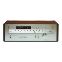
Explains the signal strength indicator on the front panel.
Details the tuning accuracy indicator on the front panel.
Identifies indicators for AM/FM reception status.
Explains the indicator for stereo FM reception.
Describes the pointer used for station tuning on the dial.
Details the switch for selecting AM or FM broadcast reception.
Explains the switch for noise elimination and mode selection.
Describes the knob used for selecting broadcast stations.
Explains the circuitry and components of the AM tuner section.
Details the circuitry and components of the FM front-end, multiplex demodulator, and filter stages.
Instructions for removing the side and top panels of the unit.
Steps to remove the bottom plate.
Procedure for removing the front panel assembly.
Identifies components visible on the front panel.
Shows parts accessible after removing the front panel.
Illustrates components visible from the top of the unit.
Identifies components on the rear panel.
Procedures for adjusting the FM tuner section for optimal performance.
Steps for adjusting the FM multiplex decoder section.
Procedures for adjusting the AM tuner section for optimal performance.
Shows an exploded view of the external parts of the unit.
Displays an exploded view of the internal components of the unit.
Lists part numbers for coils and transformers used on the PC boards.
Lists part numbers for various capacitors used on the PC boards.
Lists part numbers for transistors, ICs, and diodes used on the PC boards.
Lists part numbers for resistors used on the PC boards.
Lists part number for the LED assembly.
Lists part number for the switch assembly.
Lists part number for the fuse assembly.
Lists part number for the de-emphasis assembly.
Compares miscellaneous parts between TX-6800/KU and TX-608 variants.
Provides notes on ordering resistors and component marking conventions.
Presents the main circuit schematic diagram for the tuner.
Specifies FM performance for HE/HP models, differing from TX-6800/KU.
Lists miscellaneous specs like power requirements and dimensions for HE/HP models.