Do you have a question about the Pioneer VSX-321-K-P and is the answer not in the manual?
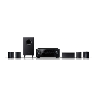
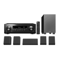
| Channels | 5.1 |
|---|---|
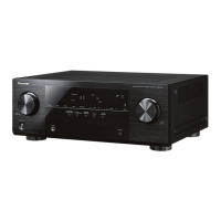
| Type | AV Receiver |
| HDMI Inputs | 4 |
| HDMI Outputs | 1 |
| Audio Formats Supported | Dolby TrueHD, DTS-HD Master Audio |
| FM Tuner | Yes |
| Weight | 7.5 kg |
| 3D Support | Yes |
| Frequency Response | 10 Hz - 100 kHz |
| Input Sensitivity | 200 mV |
| Signal-to-Noise Ratio | 98 dB |
| Video Inputs | Composite, Component |
| Audio Inputs | Analog, Digital Optical, Digital Coaxial |
| HDMI Version | 1.4 |
| USB Port | No |
| Bluetooth | No |
| Wi-Fi | No |
| Ethernet | No |
| Video Outputs | Composite |
| HDMI Features | ARC, CEC |
| Power Output | 100 W per channel |
General safety advice for service technicians and users. It includes measures to prevent shock hazards.
Details special safety characteristics of electrical components and replacement parts to prevent hazards.
Guidelines for using lead-free solder and appropriate soldering irons for environmental protection.
Information on parts that are difficult to replace as discrete components and require whole assembly replacement.
References for detailed procedures on discharging and ground point connection for safety.
Procedures to confirm product quality after servicing, covering video and audio checks.
Lists required jigs for diagnosis and firmware updates, with part numbers and remarks.
Illustrates the interconnections between major assemblies and connectors of the system.
Step-by-step troubleshooting guide for DSP-related issues, covering preliminary checks and component diagnosis.
Basic troubleshooting steps for HDMI issues like no display or sound.
Initial checks for HDMI connectivity and secure connections before proceeding.
Instructions for connecting source and sink equipment for HDMI troubleshooting.
Pin arrangement and block diagram for the EP94A1K IC, used in the D-MAIN ASSY.
How to enter and view protection detection counts on the display.
Procedures for safely disassembling the VSX-321-K-P unit, including capacitor discharging.
Detailed steps for discharging capacitors in the MAIN Assy and FL-30V sections.
Important check for connecting MAIN Assy to D-MAIN Assy before powering on.
Crucial step to connect the main capacitor GND wire to chassis during reassembly.
Step-by-step guide to remove and detach the front panel assembly.
Instructions for removing the chassis back cover.
Steps to disassemble the main assembly, including removing the G-T Assy.
Guidance on the correct orientation of the speaker during attachment.
Instructions for removing front and surround speakers, with figures.
Instructions for removing the center speaker, with figures.
Procedures for updating firmware for microcomputers, including necessary tools.
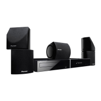
Illustrates the packing contents and methods for different speaker models.
Schematic diagram for the input assembly, detailing component connections.
PCB connection diagram for the INPUT ASSY, showing component placement.
Details differences in PCB assemblies for various models.
Lists various PCB assemblies and their corresponding part numbers.