Playback Adjustment
(1) Head Azimuth Adjustment
• Do not switch between forward and reverse operation with the screwdriver inserted.
Deck ΙΙ
Step Mode
Input Signal/
Test Tape
Adjusting Points
Measurement
Points
Adjustment
Value
Remarks
1 PLAY
STD-331E test tape
(Playback: 10kHz,
–20dB)
Deck Ι
Head azimuth
adjustment
screw (Fig. 5)
TAPE TEST
POINT (L, Rch)
(AF Assy)
Max. playback
signal level
After adjustment, apply silicon bond to
the head azimuth adjustment screw.
(2) Playback Level Adjustment
• Since this adjustment determines playback dolby NR level, perform it carefully.
Deck ΙΙ
Step Mode
Input Signal/
Test Tape
Adjusting Points
Measurement
Points
Adjustment
Value
Remarks
1
PLAY
STD-331E test tape
(Playback: 315Hz, 0dB)
Deck Ι
VR2303 (L ch)
VR2304 (R ch)
VR2305 (L ch)
VR2306 (R ch)
TAPE TEST
POINT (L, Rch)
(AF Assy)
– 3.7dBV ± 2dB
0 dB
–20 dB
30s
0 dB: 315 Hz, 250 nwb/m
315Hz
6.3kHz 10kHz 315Hz 14kHz
12.5
kHz
6.3
kHz
500
Hz
250
Hz
125
Hz
10kHz
8kHz 4kHz 2kHz
63Hz 40Hz
1kHz
30s 30s 30s 10s 10s ......................................................................................................... 10s
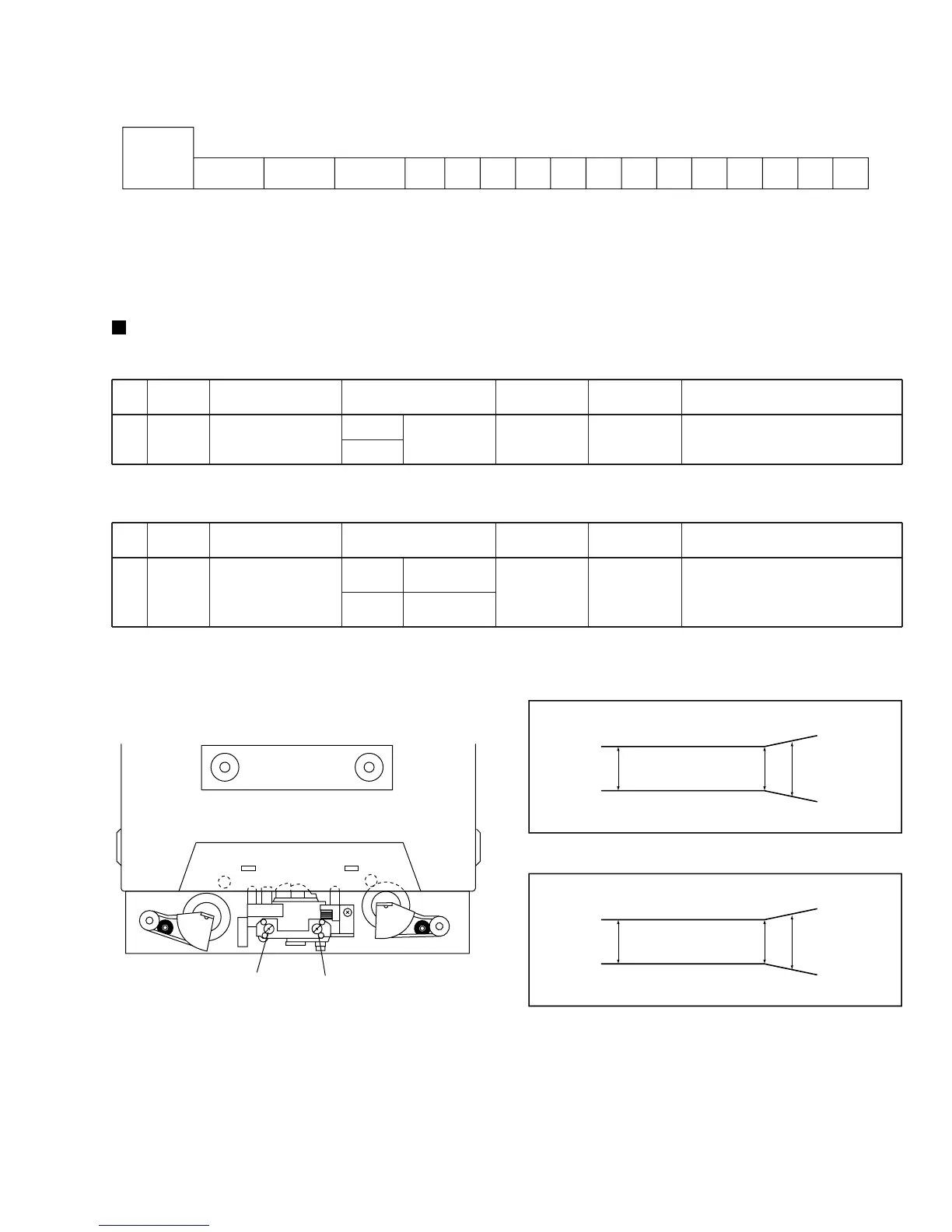
Fig.4 STD-331E Test Tape
Fig. 5 Head Azimuth Adjustment Screw
Fig. 6 Frequency Characteristics
PLAYBACK
250 10k
12.5k
3dB 3dB 4dB
REV Azimuth Adjustment Screw
FWD Azimuth Adjustment Screw
RECORDING
250 10k
12.5k
3dB 3dB 5dB
 Loading...