XR-VS88, XR-VS66
30
5. ADJUSTMENT (FOR XR-VS66/DBDXJ)
Note : Adjustment of XR-VS66/DBDXJ are the same as those of XR-A370/KUCXJ except for the following:
Step No.
Adjustment
Title
Reception
Frequency
Display
Specifications
Adjustment
Location
Frequency
(MHz)
Input Level
(dBµV/EMF)
1
AM Front End
Sensitivity
Adjustment
AM SG (400Hz, 30% Mod.)
AM Tuner SW Section
Set the mode selector to SW2.
Connect the wiring as shown in Fig. 1.
L630314MHz14 25-35
Adjust so that the DC voltage between the
IC6201-Pin 20 and GND becomes at maximum
level.
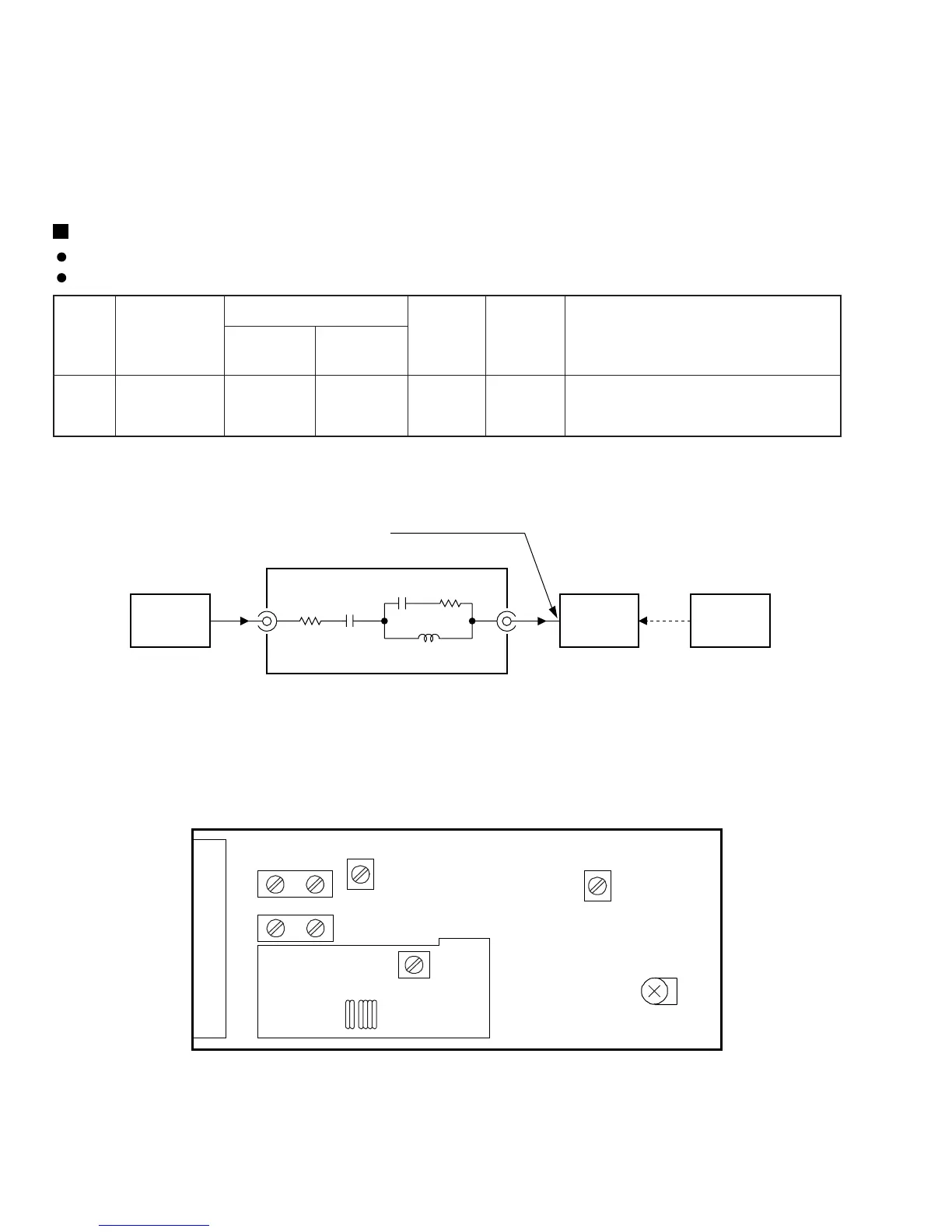
Befor adjustment, connect AM-ANT. and IEC-dummy ANT.. Signal input is through IEC-dummy ANT.. Connecting AM-ANT. follows Fig. 1.
AM SG
400pF 320Ω
20µH
125pF
R
IEC dummy
R is 30Ω when SG output is 50Ω, 5Ω when SG output is 75Ω.
PRODUCT
AM antenna terminal
DC
voltmeter
FM/AM TUNER MODULE (AXQ7062)
L6402
L6401
T6401
T6201
VR6201
AM
antenna
terminal
FM
antenna
terminal
YELLOW BLACK
L6303
GRAY BLACK
Fig. 2 Adjustment points
Fig. 1 SW adjustment wiring diagram
 Loading...