SECTION 7
PA-28-181, ARCHER III DESCRIPTION & OPERATION
SECTION 7
PA-28-181, ARCHER III DESCRIPTION & OPERATION
ISSUED: JULY 12, 1995 REPORT: VB-1611
7-5
ISSUED: JULY 12, 1995 REPORT: VB-1611
7-5
7.9 FLIGHT CONTROLS
Dual controls are provided as standard equipment, with a cable system
used between the controls and the surfaces. The horizontal tail (stabilator) is
of the all-movable slab type with a trim tab mounted on the trailing edge of
the stabilator to reduce the control system forces. This tab is actuated by a
control wheel on the floor between the front seats (Figure 7-3).
A rudder trim adjustment is mounted on the right side of the pedestal
below the throttle quadrant and permits directional trim as needed in flight
(refer to Figure 7-5).
The flaps are manually operated and spring-loaded to return to the up
position. A past-center lock incorporated in the actuating linkage holds the
flap when it is in the up position so that it may be used as a step on the right
side. The flap will not support a step load except when in the full up position,
so it must be completely retracted when used as a step. The flaps have three
extended positions, 10, 25 and 40 degrees.
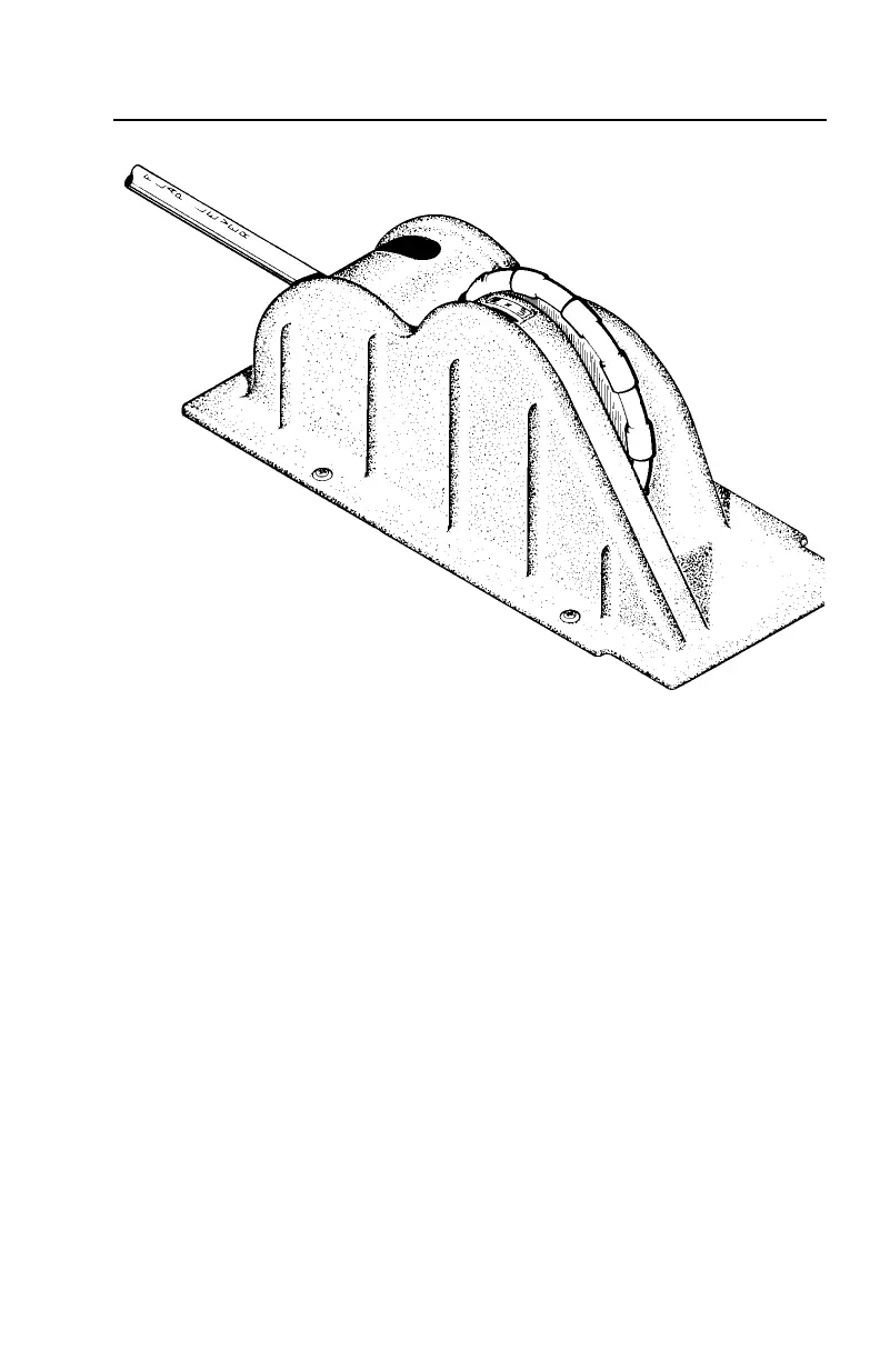
FLIGHT CONTROL CONSOLE
Figure 7-3
7.9 FLIGHT CONTROLS
Dual controls are provided as standard equipment, with a cable system
used between the controls and the surfaces. The horizontal tail (stabilator) is
of the all-movable slab type with a trim tab mounted on the trailing edge of
the stabilator to reduce the control system forces. This tab is actuated by a
control wheel on the floor between the front seats (Figure 7-3).
A rudder trim adjustment is mounted on the right side of the pedestal
below the throttle quadrant and permits directional trim as needed in flight
(refer to Figure 7-5).
The flaps are manually operated and spring-loaded to return to the up
position. A past-center lock incorporated in the actuating linkage holds the
flap when it is in the up position so that it may be used as a step on the right
side. The flap will not support a step load except when in the full up position,
so it must be completely retracted when used as a step. The flaps have three
extended positions, 10, 25 and 40 degrees.
FLIGHT CONTROL CONSOLE
Figure 7-3