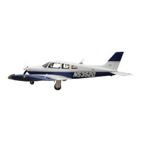
Do you have a question about the Piper TURBO ARROW III and is the answer not in the manual?
Provides an overview of the service and maintenance procedures for the PA-28R-201T and 28R-201 Cherokee aircraft.
Details the coverage of the manual, including routine service, inspections, and maintenance instructions for various systems.
Covers routine handling and servicing procedures, component locations, ground handling, and lubrication.
Details recommended nut torques derived from oil-free cadmium plated threads for airframe installations.
Covers essential information for handling the airplane while on the ground, including jacking and towing.
Details inspection procedures broken into eight major groups, specifying intervals and items to perform.
Outlines a preflight inspection for the pilot or mechanic, covering various aircraft components.
Describes the process for removing the wing, including disconnecting control cables, fuel lines, and landing gear hydraulic lines.
Details the installation of the wing, including aligning spar bolts, torqueing nuts, and connecting various systems.
Outlines structural repair methods according to FAA Advisory Circular 43.13-1A, including skin material usage.
Provides procedures for removing primary and balance control cables from fuselage and wings.
Details the installation of primary and balance control cables, including pulley routing and tension adjustment.
Explains checking and adjusting aileron rigging, including bellcrank neutral position and cable tension.
Explains checking and setting stabilator travel and control cable tension.
Explains checking and setting stabilator trim cable tension and rigging.
Explains checking and setting rudder travel and cable tension.
Explains adjusting flap up stop, step lock, control tension, and checking flap operation.
Addresses hydraulic system malfunctions, categorizing problems into supplying and landing gear hydraulic systems.
Details the removal of the hydraulic pump and reservoir by disconnecting electrical leads and hydraulic lines.
Covers cleaning, inspection, and repairs for Prestolite hydraulic pump components, focusing on O-rings and brushes.
Outlines the test equipment and procedures for testing and adjusting the Prestolite hydraulic pump.
Provides instructions for installing the hydraulic pump, including shock mounts, lines, and electrical leads.
Addresses the gear back-up extender actuator assembly, with warnings and notes for compliance with Piper Service Bulletins.
Details the removal of the back-up extender actuator located under the rear seat.
Covers positioning the gear back-up extender actuator against mounting brackets and installing attaching screws.
Provides procedures for checking and adjusting the gear back-up extender actuator, including diaphragm failure and spring tension.
Covers cleaning, inspecting, and repairing nose gear actuating cylinder parts for damage and wear.
Covers attaching the cylinder, operating rod end, hydraulic lines, and checking adjustment.
Covers cleaning, inspecting, and repairing main gear actuating cylinder parts for damage and wear.
Covers attaching the cylinder, operating rod end, downlock spring, and hydraulic lines.
Outlines testing procedures for the hydraulic system, including gear and flap operations.
Lists mechanical, electrical, and switch troubles peculiar to the landing gear system.
Covers cleaning, inspecting, and repairing nose gear oleo components for wear and damage.
Details the removal of the nose landing gear assembly, including disconnecting springs and links.
Provides instructions for installing the nose landing gear, including steering bellcrank and gear housing.
Details the adjustment of the nose gear up stop and hydraulic actuator rod.
Covers adjustment of the nose gear up stop and hydraulic actuator rod for PA-28R-201T.
Provides procedures for aligning the nose gear, including chalk lines and rudder pedal adjustments.
Details adjustment of PA-28R-201 and PA-28R-201T nose gear doors for proper closure.
Covers cleaning, inspecting, and repairing main gear oleo components for wear and damage.
Details the removal of the main landing gear assembly, including disconnecting springs and links.
Provides instructions for installing the main landing gear, including gear support bearings and housing.
Details the adjustment of the main landing gear oleo housing and downlock mechanism.
Provides procedures for aligning the main landing gear wheels, including toe-in/toe-out correction.
Details adjustment of main gear door assembly for proper closure.
Details adjustment of the nose gear up limit switch mounted on the engine mount.
Provides procedures for adjusting the nose gear down limit switch on the engine mount.
Details adjustment of the main gear down limit switch mounted on the lower drag link.
Covers adjustment of the landing gear safety switch so it actuates within the last quarter of an inch of gear extension.
Details the function of the warning switch, activating horn and red light when gear is not down/locked.
Lists suggestions for working on the power plant, including tagging parts and cleaning before assembly.
Refers to Table VIII-III for power plant troubles, causes, and remedies.
Details the removal of the propeller, including safety precautions and spinner removal.
Covers cleaning, inspecting, and repairing propeller components, including blades and hub.
Provides procedures for installing the propeller, including safety precautions and torque specifications.
Explains checking propeller blade track for excessive difference, indicating bent blades or improper installation.
Explains checking and adjusting the propeller governor for high RPM and control system settings.
Details the removal of the engine, including disconnecting electrical switches, fuel lines, and controls.
Provides procedures for installing the engine, including shock mounts, lines, and controls.
Provides procedures for removing the turbocharger assembly, including oil lines and air ducts.
Details installing the turbocharger assembly, aligning exhaust and induction connections.
Provides instructions for cleaning the air filter element and filter box assembly.
Details inspection of contact assemblies, cam follower felt, and distributor block for wear and damage.
Lists suggestions for working on the power plant, including tagging parts and cleaning before assembly.
Refers to Table VIIIA-II for engine troubles, causes, and suggested remedies.
Details propeller removal, including safety precautions and spinner removal.
Covers cleaning, inspecting, and repairing propeller components, including blades and nuts.
Provides procedures for installing the propeller, including safety precautions and torque specifications.
Explains checking propeller blade track for excessive difference, indicating bent blades or improper installation.
Explains checking and adjusting the propeller governor for high RPM and control system settings.
Details the removal of the engine, including disconnecting electrical switches, fuel lines, and controls.
Provides procedures for installing the engine, including shock mounts, lines, and controls.
Details the adjustment of throttle and mixture controls for proper operation and linkage.
Details the adjustment of idle speed and mixture for proper engine operation.
Details inspection of contact assemblies, cam follower felt, and distributor block for wear and damage.
Details the removal of the magneto, including disconnecting leads and harness plate.
Explains checking internal timing of the magneto using a timing kit or cast-in marks.
Provides procedures for installing and timing the magneto to the engine.
Details inspection of lead assemblies for physical damage and checks for continuity and insulation.
Provides procedures for removing spark plugs, including handling seized plugs.
Covers visual inspection for defects and cleaning of spark plugs.
Details installing spark plugs, including anti-seize compound and torque specifications.
Refers to Table IX-III for fuel system troubles, causes, and suggested remedies.
Covers inspection and repair of fuel tanks, including checking for peeling sloshing compound.
Provides procedures for installing fuel tanks, including connecting sender wires and fuel lines.
Explains checking fuel quantity transmitter units and gauges while installed in the airplane.
Provides procedures for adjusting the auxiliary fuel pump system.
Outlines operational checks for the auxiliary fuel pump system.
Provides procedures for adjusting the electric fuel pump on a bench test.
Details adjusting the electric fuel pump while installed in the airplane.
Provides procedures for installing the fuel pump, including cover and fuel lines.
Details inspecting and tightening fuel line union fittings for leaks and proper torque.
Provides procedures for adjusting the vacuum regulator valve for proper vacuum pressure.
Refers to Table X-I for troubleshooting tips related to the vacuum system.
Refers to Table X-II for troubleshooting the gyro horizon indicator.
Refers to Table X-III for troubleshooting the gyro horizon indicator.
Refers to Table X-IV for troubleshooting the rate of climb indicator.
Refers to Table X-V for troubleshooting the altimeter.
Refers to Table XI-V for electrical system troubles, causes, and remedies.
Provides procedures for testing the alternator system by switching loads and observing ammeter output.
Details connecting a test ammeter to measure current flowing through the rotor coil.
Provides procedures for testing the alternator internal field circuit for a short circuit.
Details testing the positive case rectifiers using a special test box tool.
Covers testing the negative case rectifiers in the end shield.
Covers testing stator coils for ground using a 110-volt test lamp.
Outlines bench run-up test procedures for the alternator, including field excitation.
Details testing the hot stabilized output of the alternator.
Provides procedures for checking alternator belt tension using a torque wrench.
Provides precautions for testing or servicing the alternator, emphasizing polarity and avoiding shorts.
Covers overhaul procedures for the alternator, including disassembly and testing.
Covers inspection and testing of alternator components: rotor, rectifiers, and stator.
Outlines precautions and procedures for testing the ELT transmitter.
Provides procedures for testing the pilot’s remote switch.
Provides maintenance information for the heater system, including exhaust manifold inspection and control operation.
Provides methods for detecting system malfunctions by interpreting gauge readings.
Covers refrigerant safety precautions and system servicing procedures.
Covers methods for checking the system for leaks using detector solution or electronic leak detector.
Provides steps for leak checking using a manifold gauge set and refrigerant pressure.
Details a second method for leak checking using a charging hose and refrigerant.
Provides procedures for evacuating the system to remove trapped air and moisture.
Outlines procedures for charging the system after evacuation.
Describes the preferred method of charging the system using a charging stand.
Covers checking the compressor oil level for York and Sankyo compressors.
Provides procedures for adjusting drive belt tensions for York and Sankyo compressors.
Explains rigging instructions for the condenser assembly, including push rod adjustment.
Details the air conditioning throttle switch and its adjustment procedures.
Refers to Table XIV-VI for troubleshooting the oxygen system.
Provides recommended inspection and maintenance information for oxygen system parts.
Covers cleaning and purging oxygen system components, emphasizing cleanliness.
Recommends solutions for leak testing and procedures for checking connections.
Provides procedures for refilling the oxygen system, emphasizing safety and qualified personnel.
Refers to Table XIV-VI for troubleshooting the oxygen system.
| Manufacturer | Piper Aircraft |
|---|---|
| Model | Turbo Arrow III |
| Horsepower | 200 hp |
| Max Takeoff Weight | 2, 900 lbs |
| Fuel Capacity | 72 gallons |
| Service Ceiling | 20, 000 ft |
| Seating Capacity | 4 |
| Type | Single-engine piston |
| Propeller | Constant-speed |
| Landing Distance | 1, 200 ft |


