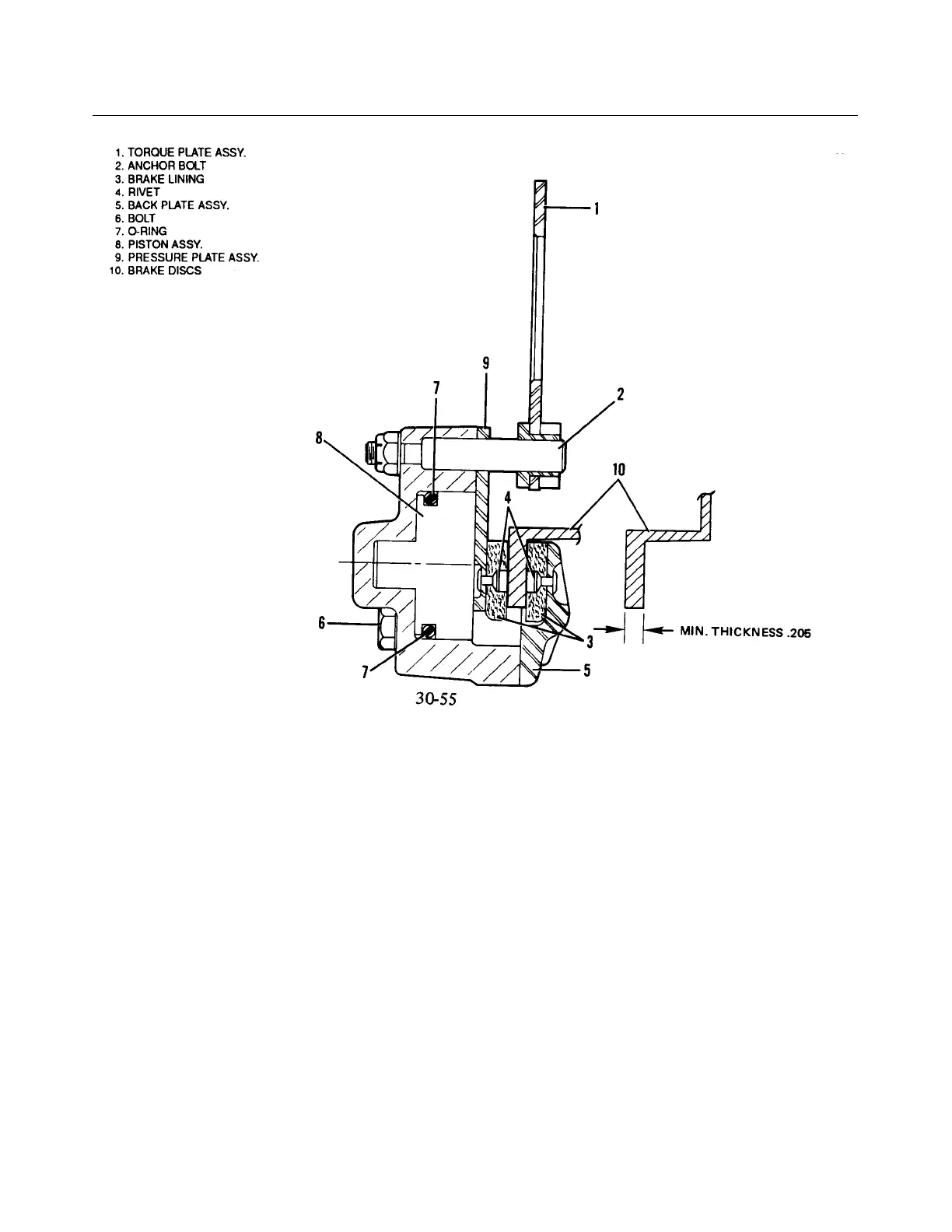
Figure 7-18. Wheel Brake Assembly
7-51. BRAKE SYSTEM.
7-52. WHEEL BRAKE ASSEMBLY.
7-53. BRAKE ADJUSTMENT AND LINING TOLERANCE. No adjustment of the brake lining clearance is
necessary as they are self adjusting. Inspection of the lining is necessary and it may be inspected visually while
installed on the airplane. The linings are of the riveted type and should be replaced if the thickness of any one
segment becomes worn below .100 of an inch or unevenly worn.
7-54. REMOVAL AND DISASSEMBLY OF WHEEL BRAKE ASSEMBLY. (Refer to Figure 7-18.)
a. To remove the brake assembly, first disconnect the brake line from the brake cylinder at the tube
fitting.
b. Remove the cap bolts that join the brake cylinder housing and the lining back plate assembly. Remove
the back plate from between the brake disc and wheel.
c. Slide the brake cylinder housing from the torque plate.
d. Remove the pressure plate by sliding it off the anchor bolts of the housing.
Revised: 2/13/89
1K13
* CHEROKEE ARROW III SERVICE MANUAL
LANDING GEAR AND BRAKE SYSTEM
 Loading...


