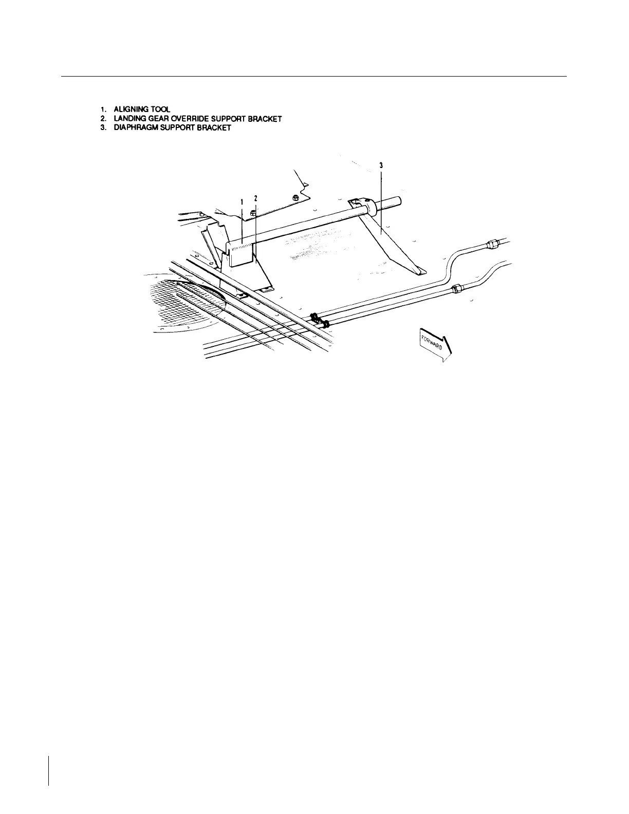
Figure 6-5. Checking Aligning Brackets of Gear Back-Up Extender Actuator
6-13. INSTALLATION OF GEAR BACK-UP EXPENDER ACTUATOR ASSEMBLY. (Refer to Figure 6-6.)
a. Position the gear back-up extender actuator against its mounting brackets and install attaching machine
screws. Do not tighten screws.
NOTE
With the base attached and before installing the attaching screw through
the ring of the diaphragm housing, ensure that the attaching holes in the
housing and mounting bracket align without using force. Should they
misalign, it may be necessary to reform the main fuselage mounting
bracket.
To reform the main fuselage mounting bracket, an Aligning Tool may be
used. (Refer to Figure 6-5.) This tool may be fabricated from dimensions
given in Figure 6-10. When proper alignment has been accomplished,
tighten the machine screws.
b. Move the actuator on its mounting brackets to allow the manual control push rod to have maximum
clearance from the left stabilator cable and center in the fairlead on the aft face of the main spar box.
Check system for sufficient travel and freedom of movement of controls. Tighten actuator attaching
screws.
Revised: 2/13/89
1H21
* CHEROKEE ARROW III SERVICE MANUAL
HYDRAULIC SYSTEM
 Loading...


