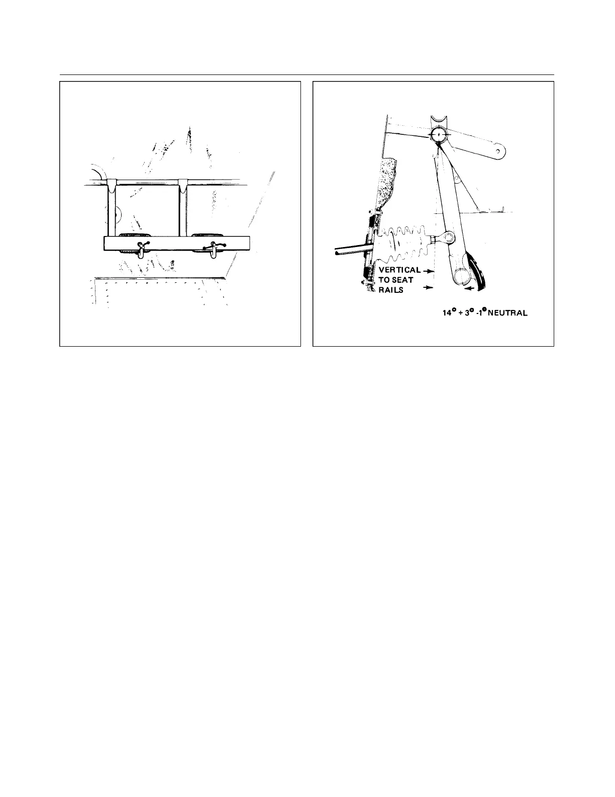
Figure 7-5. Clamping Rudder Pedals in Figure 7-6. Rudder Pedals at Neutral
Neutral Position Angle
g. Extend a chalk line from the mark on the floor below the tail skid to a point approximately three feet
forward of the nose wheel. Allow the line to pass under the wheel at the center line of the tire. Snap
the chalk line.
h. Clamp the rudder pedals to align them in a lateral position. Ascertain that the rudder pedals are in their
neutral position. (Refer to Figure 7-6.)
i. Adjust the rod end bearings of each steering control rod to align the nose wheel with the chalk line and
to bring the rudder pedals into neutral angle fore and aft.
j. Install the steering push rods on the pilot’s rudder pedals. Adjust the rods so the lengths are both the
same and the rudder pedals are at their neutral position.
k. To align the nose wheel straight forward, stand in front of the nose gear and align the center rib of the
tire with the chalk line, or lay a straight edge along the side of the tire and parallel the straight edge
with the chalk line.
l. Install the nose wheel bungees in their neutral position (no load on the bungee springs). Adjust bungee
rod ends as necessary.
m. Place a bubble protractor against a rudder pedal steering tube to check the neutral angle as shown in
Figure 7-6.
n. One end of each rod must be disconnected and the jam nuts loosened to make any adjustments. Do not
attempt to make the adjustment by means of one rod end bearing, but divide the adjustment between
the bearings at each end of each rod. Check that the rod ends have sufficient thread engagement by
ascertaining that a wire will not go through the check hole in the rod. Reinstall the rods and tighten the
jam nuts.
o. To check the nose gear steering for its 30° +/- 2° maximum right and left travel, mark on each side of
the nose wheel an angle line from the centerline and wheel pivot point. Turn the wheel to its maximum
-travel in both directions to check for allowable travel. Should travel be exceeded in one direction and
not enough in the other direction, check for possible damage to the gear fork or torque links.
Revised: 2/13/89
1J12
* CHEROKEE ARROW III SERVICE MANUAL
LANDING GEAR AND BRAKE SYSTEM
 Loading...


