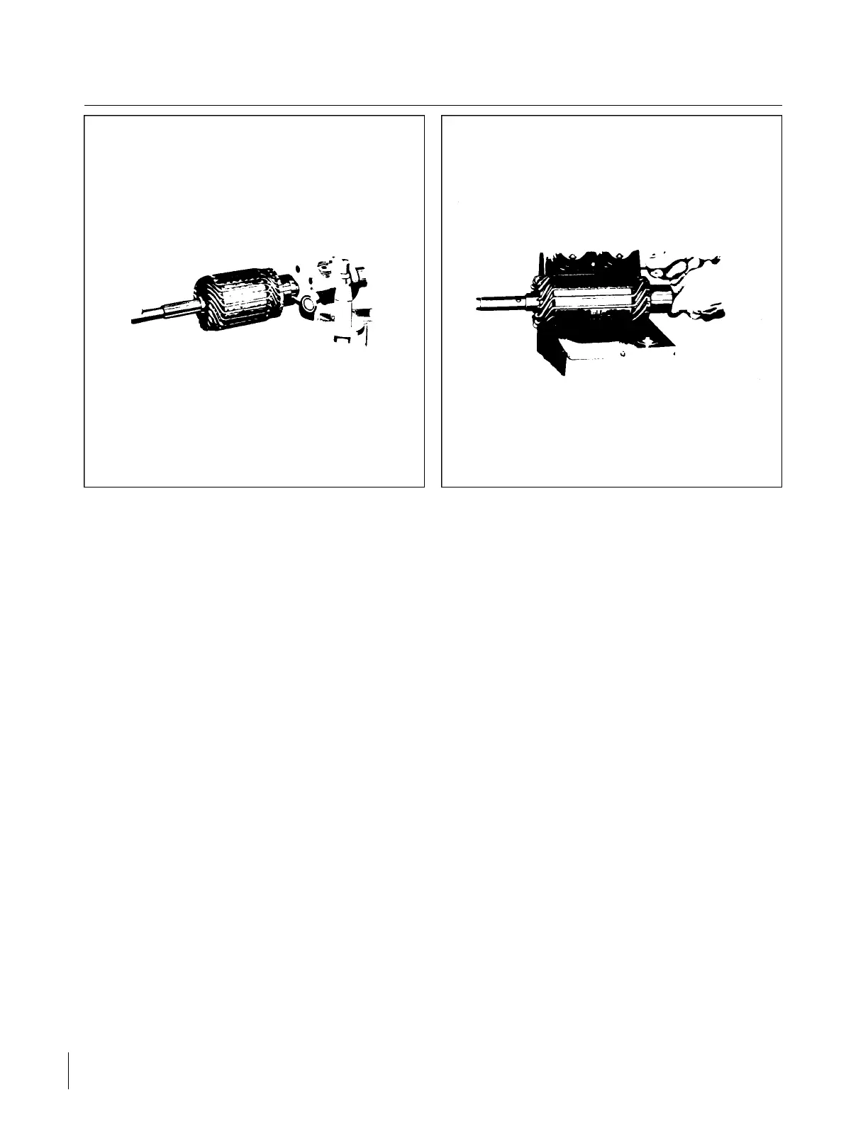
Figure 11-39. Turning Starting Motor Figure 11-40. Testing Motor Armature for
Commutator Short
11-53. DISASSEMBLY.
a. Disassembly of starter motor used on PA-28R-201 airplanes is as follows:
1. Remove the frame screws from the commutator end head and pull end head and armature from
frame. Lift the brushes and lock in elevated position with brush springs. Use a puller to remove the
end head from the armature. Use a special bearing puller to remove the sealed ball bearing from
the armature shaft
2. Remove the frame screws that secure the gear housing to the frame. Remove bolts and nuts
holding the gear housing to the pinion housing and separate the two units. Pull Bendix shaft from
pinion housing. Do not lose the steel spacer that is located on the pinion end of the shaft. Remove
reduction gear, woodruff key and steel spacer from shaft.
3. Turn the Bendix pinion until it locks in the extended position. Locate spirol pin and use a punch to
remove. Slide drive assembly off the shaft. Do not attempt to disassemble the drive and do not dip
it in cleaning solvent.
4. To remove the roller bearings from the gear housing, use an arbor press and the correct bearing
arbor. DO NOT HAMMER OUT. Each part should be cleaned and inspected for excessive wear or
damage. Bearings should be checked for proper clearance and evidence of roughness or galling.
Oil and dirt should be removed from insulation and the condition of the insulation checked.
b. Disassembly of starter motor used on PA-28R-201T airplanes is as follows:
1. Remove the safety wire and thru bolts from the commutator end and pull the end head from the
frame.
2. Pull the drive end head and armature from the frame and separate the drive end head from the
armature.
3. The drive end bearing may be removed by pressing out of the drive end head.
4. Each part should be cleaned and inspected for excessive wear or damage. Bearing should be
checked for proper clearance and evidence of roughness or galling. Oil and dirt should be removed
from insulation and the condition of the insulation checked.
Revised: 2/13/89
2H23
CHEROKEE ARROW III SERVICE MANUAL
ELECTRICAL SYSTEM
 Loading...


