SECTION 7
DESCRIPTION & OPERATION PA-28-181, ARCHER III
SECTION 7
DESCRIPTION & OPERATION PA-28-181, ARCHER III
REPORT: VB-1611 ISSUED: JULY 12, 1995
7-8
REPORT: VB-1611 ISSUED: JULY 12, 1995
7-8
The fuel drains should be opened daily prior to first flight to check for
water or sediment and proper fuel. Each tank has an individual drain at the
bottom, inboard rear corner.
A fuel strainer, located on the lower left front of the fire wall, has a drain
which is accessible from outside the nose section. The strainer should also be
drained before the first flight of the day. Refer to paragraph 8.21 for the
complete fuel draining procedure.
A dual fuel quantity gauge is located in lower center of the instrument
panel.
An electric engine priming system is provided to facilitate starting. The
primer switch is located in the far left side of the overhead switch panel
(refer to Figure 7-15A).
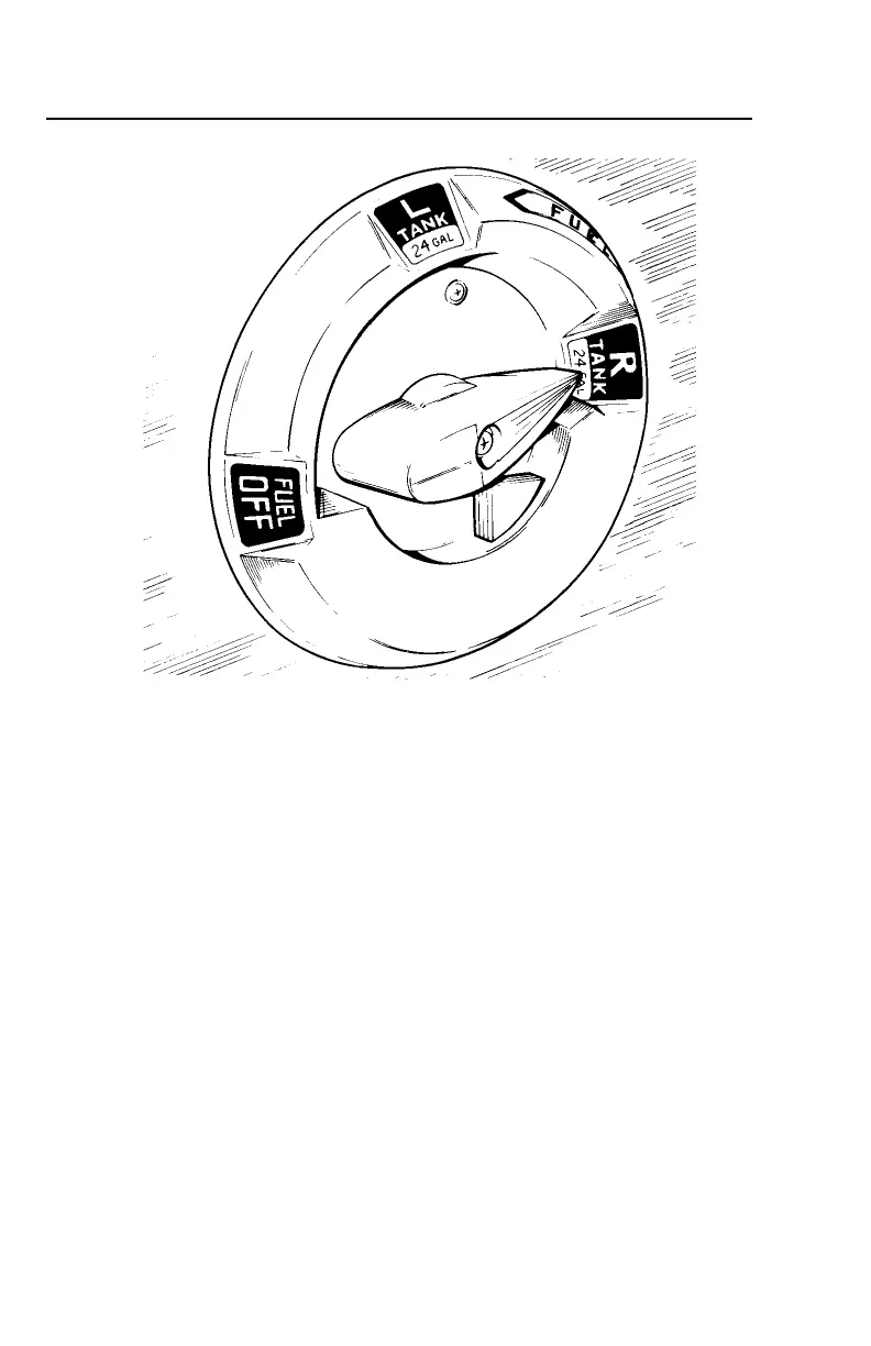
FUEL SELECTOR
Figure 7-7
The fuel drains should be opened daily prior to first flight to check for
water or sediment and proper fuel. Each tank has an individual drain at the
bottom, inboard rear corner.
A fuel strainer, located on the lower left front of the fire wall, has a drain
which is accessible from outside the nose section. The strainer should also be
drained before the first flight of the day. Refer to paragraph 8.21 for the
complete fuel draining procedure.
A dual fuel quantity gauge is located in lower center of the instrument
panel.
An electric engine priming system is provided to facilitate starting. The
primer switch is located in the far left side of the overhead switch panel
(refer to Figure 7-15A).
FUEL SELECTOR
Figure 7-7