5 59324 V0605
Finish Gate Setup
1. Place the finish gate over both lanes at the finish end of
the track. For the elevated track, insert four of the pull
pins into the holes on both sides of each finish gate leg.
Place the gate on the track so the pins rest on top of the
track sides.
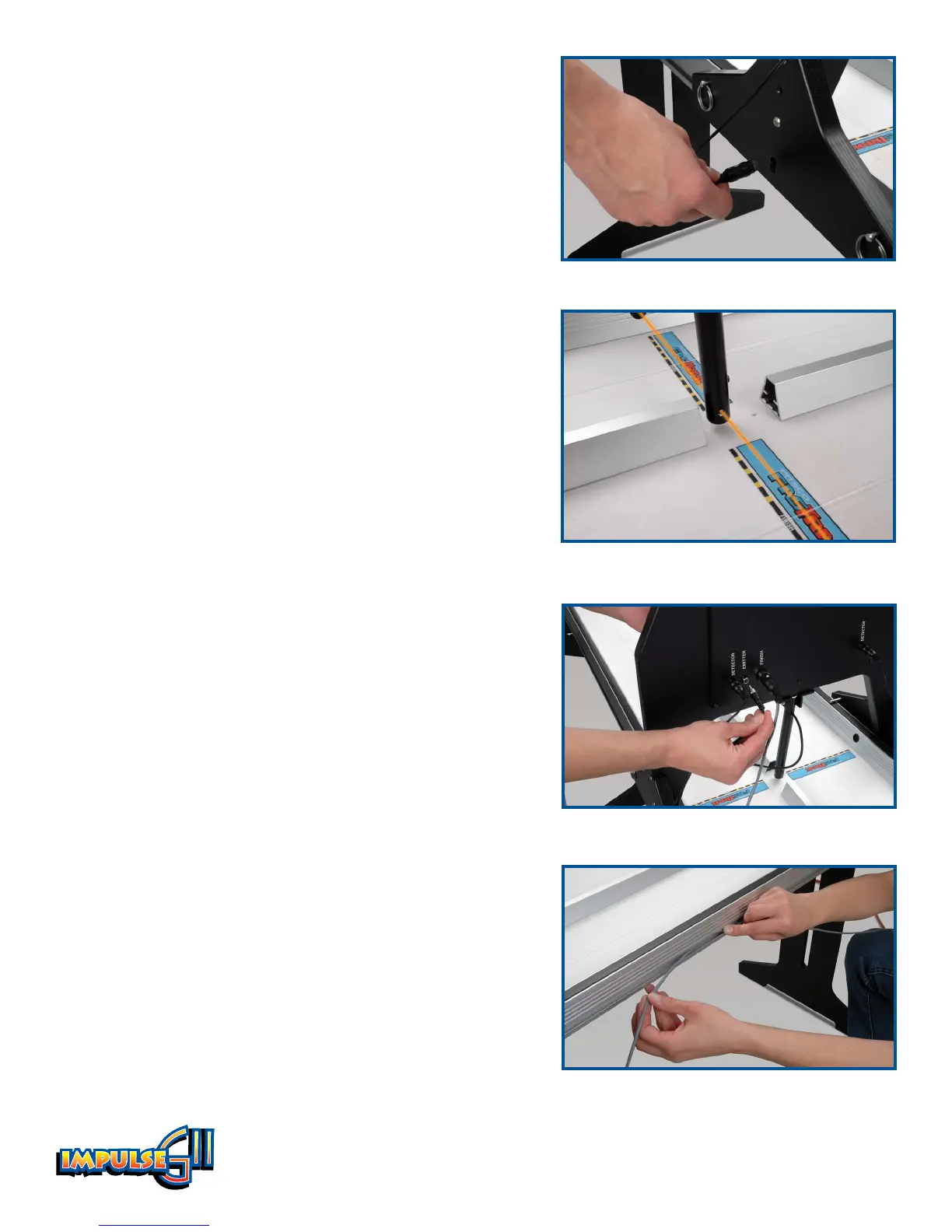
2. Insert the finish detector pigtails into the hole, or
socket, that is on both legs of the finish gate (Figure 5).
Note the positions of the emitter bulbs on either side
of the emitter tube, which is the tube that hangs down
from the center of the finish gate. The detectors should
be aligned with the emitter bulbs (Figure 6).
Insert the detector for Lane 1 in the upper socket and
insert the Lane 2 detector in the lower socket, corre-
sponding to the position of the emitter bulbs.
3. Plug the end of each detector pigtail into the jacks
labeled “Detector” on the back of the finish gate. When
facing the back of the finish gate, the Lane 1 detector
goes in the right jack, and the Lane 2 detector goes in
the left jack.
4. Plug the cord extending from the emitter tube into the
jack labeled “Emitter” on the back of the finish gate
(Figure 7).
5. Insert the end of the 70-foot cable into the DIN socket
labeled “Finish” on the finish gate. Routing the cable
along the right side of the track, unroll the cable and
extend it to the start end.
FasTrak Only:
6. Down the length of the track, run the DIN cable in the
conduit that is on the side of the FasTrak. Run the
cable down to the start gate and control box area
(Figure 8).
Other Track?
If you have another track, such as the metal EL 80 track,
please call Customer Service at 800-358-4983 to learn how
to use the Impulse GII system with your track.
Figure 5
Figure 6
Figure 7
Figure 8