7 59324 V0605
Prelaunch Setup
1. Locate the two deceleration towels. Fold the towels in half lengthwise one time, width-wise one
time, and lengthwise again. Place one towel in each lane on the finish end of the track approxi-
mately two feet behind the finish line. Make sure the end of the towels with the most edges
showing is facing the finish gate. Careful placement of the towels is critical to bring the cars to a
safe halt at the end of each run.
2. Make sure both launch pods are in the uncocked position before powering up the system.
(Switching on the power when the launch pods are cocked could prematurely launch the cars.)
To put the pods in the uncocked position, make sure the switch on the side of each pod is flipped
in the horizontal position.
3. Switch on the Impulse GII system by turning on the power switch on top of the control box. The
displays on the start gate should light.
If the red lights are lit on the Finish gate, then the
detectors are not aligned correctly. Move the emitter
tube forward or back until it is adjusted so the red
lights turn off.
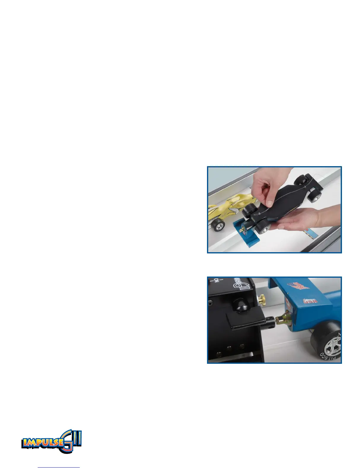
4. Detach the Lane 1 monofilament line from the start
end anchor. Thread the line through the screw eyes
of the car – thread the front screw eye first, then the
rear screw eye (Figure 13). Reconnect the line to the
anchor. Repeat for Lane 2.
Note: if you wish to stage
several other cars behind the launch pods, you can
do so before reconnecting the line to the anchor.
5. Position the cars at the start line. The front of the cars
should be aligned with the line.
6. Insert a Pitsco CO
2
cartridge in each dragster. Make
sure the cartridge is fully seated in the car’s cartridge
hole.
7. Position the launch pods at the rear of the cars so the
firing sleeve engages the neck of the CO
2
cartridges
(Figure 14). This may require a height adjustment to
the launch pods using the thumb screws on the front
of each pod. The launch pods should be secured in
place by the Velcro material.
Figure 13
Figure 14