TETRIX PULSE Controller Sensor Port Pinout Diagrams
PULSE Sensor Ports
The PULSE controller uses Arduino UNO-compatible pin assignments. The sensors that are
supported in the PULSE Arduino Library are set up automatically using the library functions.
Support for different types of sensors will be added as they become available. However,
the ports are all directly accessible using Arduino coding functions if you wish to code with
additional sensors not yet supported in the PULSE library. With the exception of the I2C
port, all can be configured as inputs or outputs using the Arduino pinMode() function. To
learn more, visit the Language Reference section at https://www.arduino.cc/en/Reference/
HomePage.
Table 1: I2C Port Pin Assignments
Pin Function Arduino Software (IDE) pin assignment ( )
Pin 1 Ground N/A
Pin 2 +5 volts, 100 mA N/A
Pin 3 SDA (I2C serial data) ADC4 input channel (A4) | digital I/O (18)
Pin 4 SCL (I2C serial clock) ADC5 input channel (A5) | digital I/O (19)
Table 2: Analog Sensor Port (A1)
Pin Function Arduino Software (IDE) pin assignment ( )
Pin 1 Ground N/A
Pin 2 +5 volts, 100 mA N/A
Pin 3 No connect N/A
Pin 4 Analog input or digital input/output Analog input (A1) | digital I/O (15)
Table 3: Analog Sensor Port (A2)
Pin Function Arduino Software (IDE) pin assignment ( )
Pin 1 Ground N/A
Pin 2 +5 volts, 100 mA N/A
Pin 3 No connect N/A
Pin 4 Analog input or digital input/output Analog input (A2) | digital I/O (16)
Table 4: Analog Sensor Port (A3)
Pin Function Arduino Software (IDE) pin assignment ( )
Pin 1 Ground N/A
Pin 2 +5 volts, 100 mA N/A
Pin 3 No connect N/A
Pin 4 Analog input or digital input/output Analog input (A3) | digital I/O (17)
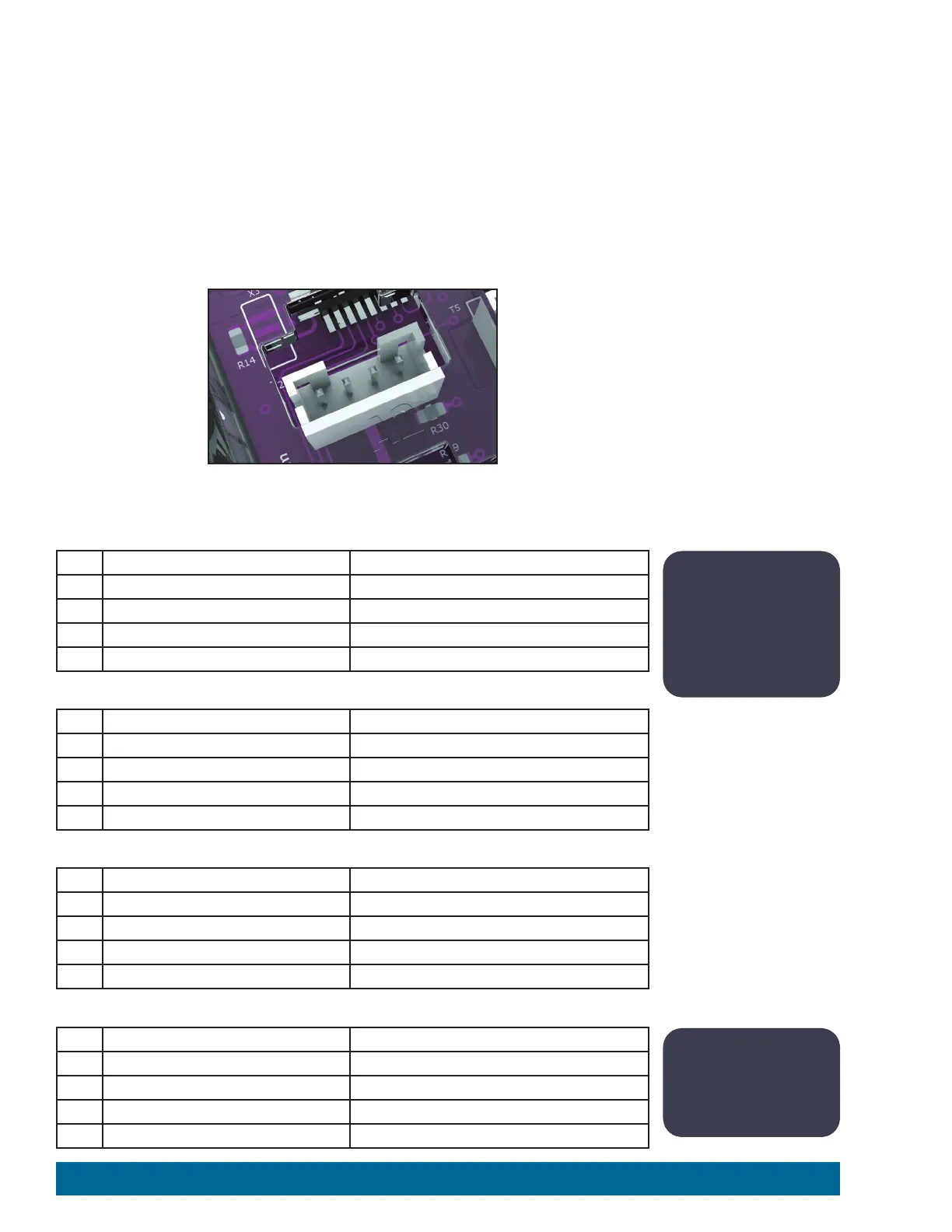
Figure 67: PULSE Sensor Port (Pins are left to right: 1, 2, 3, 4.)
Note: The PULSE I2C
port can be used
only in I2C mode. It
cannot be configured
for analog or digital
mode.
Note: Analog sensor
ports A1-A3 can also
be configured as
digital input/output.
132 Appendix
 Loading...
