Figure 26
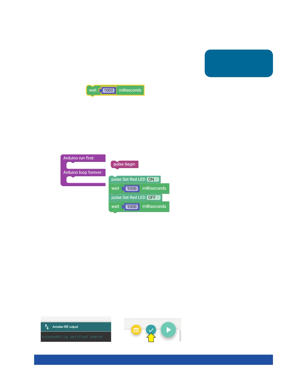
Every program starts with a setup-loop block. Under the setup portion of the
block, the pulse Begin block always comes first. Any other blocks that need to be
set up only once are placed here. Blocks that will occur in a continuous loop in the
program are placed in the loop portion of the block.
In this example, the turning on and off of the red LED occurs over and over because
it is in a loop. Only terminating the program stops the program loop (Figure 27).
Tip: The time block is located
under the Motors category in
the software.
Further Investigate
Look at the right side of the program. You see text with different punctuation. This
is called syntax, or text-based programming. Each block in the sketch is typically
represented by one line of text. Lines of text within a sketch are also known as code,
which is why programming is sometimes called coding.
You can change some parameters in the sketch to see how they affect the behavior
of the red LED. The wait block determines how long the LED will be on and off
(Figure 26). This is a parameter you can change in your sketch. Experiment with
changing those values to create new blinking behaviors for the LED. Try making the
LED blink faster or slower.
Extension Activity
With the example as a reference, try creating the blinking LED in a new sketch.
Instead of just blinking the red LED, try to blink the green LED too.
Flashing or blinking lights can be used for signaling or long-distance
communication. Challenge yourself to create a sequence of blinking LED lights like
a stoplight.
To start a new sketch, select File > New. Place the appropriate blocks into the
sketch. When you create your own sketch, there is a built-in software tool to help
ensure your code is free of errors. You can check your program by clicking Verify
the Sketch (Figure 28).
This will cause the code to compile but not upload. If there are errors in the code,
they will be displayed in the compiler error window at the bottom of the sketch
window (Figure 29). Errors will need to be corrected before code can be uploaded
to the PULSE controller.
Figure 28 Figure 29
Figure 27
Getting Started Activities 27