12
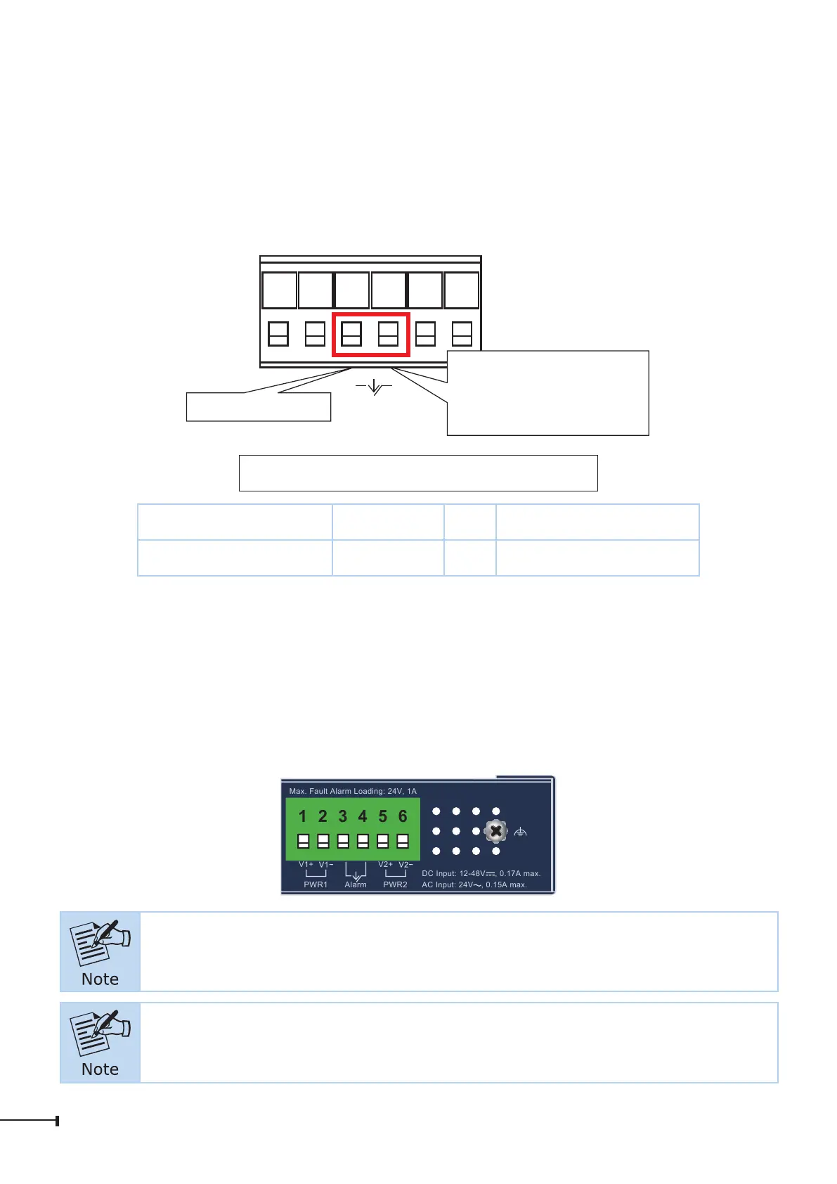
3.6 Wiring the Fault Alarm Contact
The fault alarm contacts are in the middle of the terminal block connector as the
picture shows below. Inserting the wires, the Industrial Ethernet Switch will detect
the fault status of the power failure and then forms an open circuit. The following
illustration shows an application example for wiring the fault alarm contacts.
1 2 3 4 5 6
Fault Alarm Contacts
The Fault Alarm Contacts are
energized (CLOSE) for normal
operation and will OPEN when
failure occurs
Alarm
Insert the wires into the fault alarm contacts
Wire Range Wire Type FW Torque In-lbs (N.m)
12-24 AWG Str/Sol Cu 2 5 (0.56)
Alarm relay circuit accepts up to 24V DC, 1A.
3.7 Grounding the Device
Users MUST complete grounding wired with power cord adapter or power supply
source should be connected to a socket outlet with an earthing connection;
otherwise, a sudden lightning could cause fatal damage to the device
Max. Fault Alarm Loading: 24V, 1A
DC Input: 12-48V
, 0.17A max.
AC Input: 24V
, 0.15A max.
Alarm
V1+ V2+
PWR2PWR1
1 2 3 4 5 6
EMD (Lightning) DAMAGE IS NOT COVERED UNDER WARRANTY.
LES DOMMAGES EMD (éclair) NE SONT PAS PRIS SOUS GARANTIE.
 Loading...