8
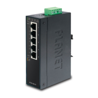
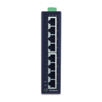
3.2 Front View
P1 P2 Alarm
ACT
LNK
10/100
1
2
3
4
5
ISW-500T
P1 P2 Alarm
ACTLNK
10/100
1
2
3
4
5
6
7
8
ISW-800T
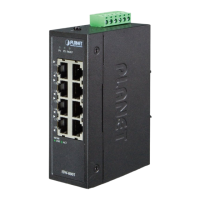
Figure 3: ISW-500T Front View Figure 4: ISW-800T Front View
3.3 LEDDenition
System
LED Color Function
DC1 Green Lights to indicate DC power input 1 has power.
DC2 Green Lights to indicate DC power input 2 has power.
Alarm Red Lights to indicate that AC or DC power has failed.
Per 10/100BASE-TX Port
LED Color Function
10/100
LNK/ACT
Green
Lights
Indicating the port is running at 10/100Mbps
and successfully established.
Blinks
Indicating that the switch is actively sending or
receiving data over that port.
 Loading...