13
2.1.1 Power over Coaxial Extender Front Panel
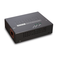
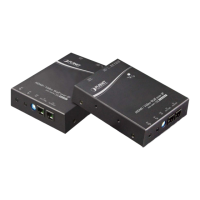
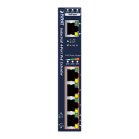
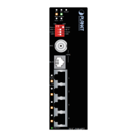
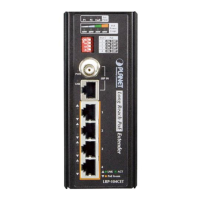
Figure 2-1 and Figure 2-2 show the front panels of the VC-203PT and
VC-203PR Industrial Power over Coaxial Extenders.
LNK
CPE
CO
Coaxial
PoE IN
PWR
OFF
ON
LNK/ACT
100
LAN
VC-203PT
PoE over Coaxial Extender
Mode Band Plan
CO Symm
CPE Asymm
Transmitter
1 2
ON
PoE IN
LNK
CPE
CO
Coaxial
PoE Out
PWR
OFF
ON
LNK/ACT
100
LAN
VC-203PR
PoE over Coaxial Extender
Receiver
Mode Band Plan
CO Symm
CPE Asymm
1 2
ON
Figure 2-1: VC-203PT front panel Figure 2-2: VC-203PR front panel
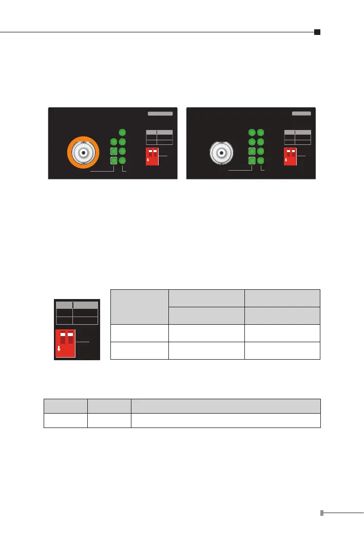
Front Panel DIP Switch Setting
The front panels of the VC-203PT and VC-203PR provide one 2-DIP
switch which is for conguring coaxial link CO/CPE mode and Band plan
function.
Refer to the table below to know about the 2-DIP switch settings and
descriptions:
OFF
ON
Mode Band Plan
CO Symm
CPE Asymm
1 2
ON
DIP-1 DIP-2
Mode Band Plan
OFF CO Symmetric
ON CPE Asymmetric
2.1.2 LED Indicators
System
LED Color Function
PWR Green Light: indicates the power is on.
 Loading...