VIP User’s Manual
Overview
3
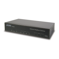
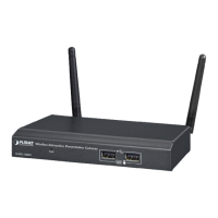
Figure 1-5 VIP-400FO Front Panel
LED Indicators
The LED indicators on the front panel display the current status of VIP as described in the following
table:
Indicator Color Activity Indication
PWR Green On Power is supplied to the gateway.
SYSTEM Green Blinking The system is running. (Heartbeat LED)
LAN
Ÿ ACT
Ÿ 100M
Ÿ LNK
Ÿ COL
Green
Green
Green
Green
On
On
Off
On
On
Data is presented on LAN.
The gateway is connected to LAN at 100Mb/s.
The gateway is connected to LAN at 10Mb/s.
The gateway is connected to LAN.
Data collision is occurring on the network connection.
Slot A
Slot B
Slot A/ Slot B
Green
Green
On
On
Blinking
A slide-in module is plugged into slot A.
A slide-in module is plugged into slot B.
The system is updating the firmware.
Slot A/B
Channels
1-4 (For VIP-
2 channels)
Green Off
On
Blinking
The line is idle.
The line is being used.
The line is ringing.
Ports
VIP is equipped with an Ethernet interface with 10/100 Mbps auto-negotiation capability. The
Ethernet interface port is located on the front panel. In addition to the Ethernet interface port, there
is a 9-pin RS-232 interface port on the front panel. Their functions are described below:
Port Label Function
RJ45 LAN Connecting VIP to a 10/100 Mbps Ethernet network
9-pin RS-232
User Console Connecting VIP to a VT-100 terminal or terminal emulator for con-
figuring VIP