5
3. Hardware Installation
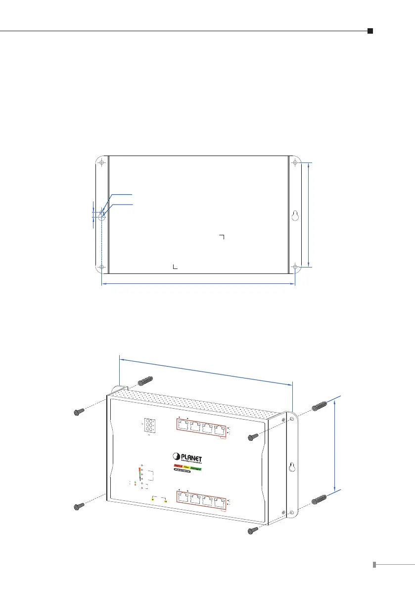
3.1 Wall Mount Installation
To install the Wall-mount Managed Switch on the wall, simply follow the following
steps:
Step 1: Drill 4 holes with 8mm diameter on the wall. The horizontal and vertical
distances between the 2 holes are 230mm and 124mm,respectively.
Ø4mm
Ø8mm
Step 2: Hammer the four anchors into the four holes.
Step 3: Then the four given screws are screwed into the anchors to nish the
wall-mountinstallation,asshownbelow.
ACTLNK
ACTLNK
1G/2.5G
100
1000 LNK/ACT
10/100 LNK/ACT
bt PoE-in-Use
at PoE-in-Use
R.O.
Ring
PWR 2
PWR 1
SFP
9
10
PWR 1
V1
V1+
PWR 2
V2
V2+
3 421 7 865
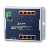
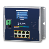
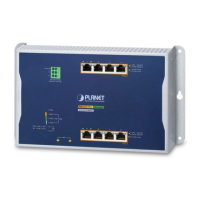
WGS-5225-8UP2SV
Managed
Fiber
SFP
9
10
Alarm
Smart LCD
DC Input Range
48-54V
, 8A max.
PoE++
Dual power input is required
for maximum PoE loading.
Max. Fault Alarm Loading: 24V, 1A
1000 LNK/ACT
10/100 LNK/ACT
bt PoE-in-Use
at PoE-in-Use
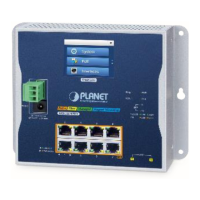
3 421
PoE++
1000 LNK/ACT
10/100 LNK/ACT
7 865
PoE+
V+
Ground
SFP
9
10
ACTLNK
ACTLNK
1000
100
120W
240W
360W
PWR
SFP
9
10
PoE Usage
DC Input Range
48-54V
, 8A max.
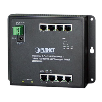
WGS-4215-8HP2S
Managed
Fiber
PoE
++
at PoE-in-Use
230mm
124mm
 Loading...