8
4. Wiring the Power Inputs
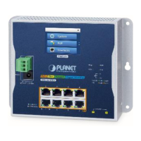
The Wall-mount Managed Switch features a strong and convenient power input
system incorporated into customer’s automation network to enhance system
uptime.
Model
Power Input Range
PWR
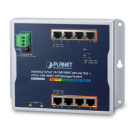
WGS-4215-8HP2S DC48-54V,8Amax
Note: Maximum power requirements also rely on the real site application.
1000 LNK/ACT
10/100 LNK/ACT
bt PoE-in-Use
at PoE-in-Use
3 421
PoE++
1000 LNK/ACT
10/100 LNK/ACT
7 865
PoE+
V+
Ground
SFP
9 10
ACTLNK
ACTLNK
1000
100
120W
240W
360W
PWR
SFP
9
10
PoE Usage
DC Input Range
48-54V
, 8A max.
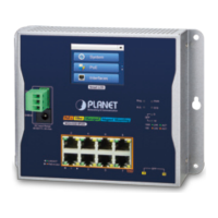
WGS-4215-8HP2S
ManagedFiberPoE
++
at PoE-in-Use
10/100/1000BASE-T 802.3at PoE
+
RJ45 Port
10/100/1000BASE-T 802.3bt PoE
++
RJ45 Port
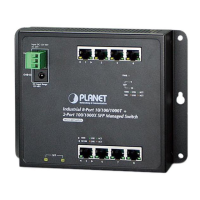
3-pin Spring Terminal Block
V+
Ground
DC Input Range
48-54V
, 8A max.
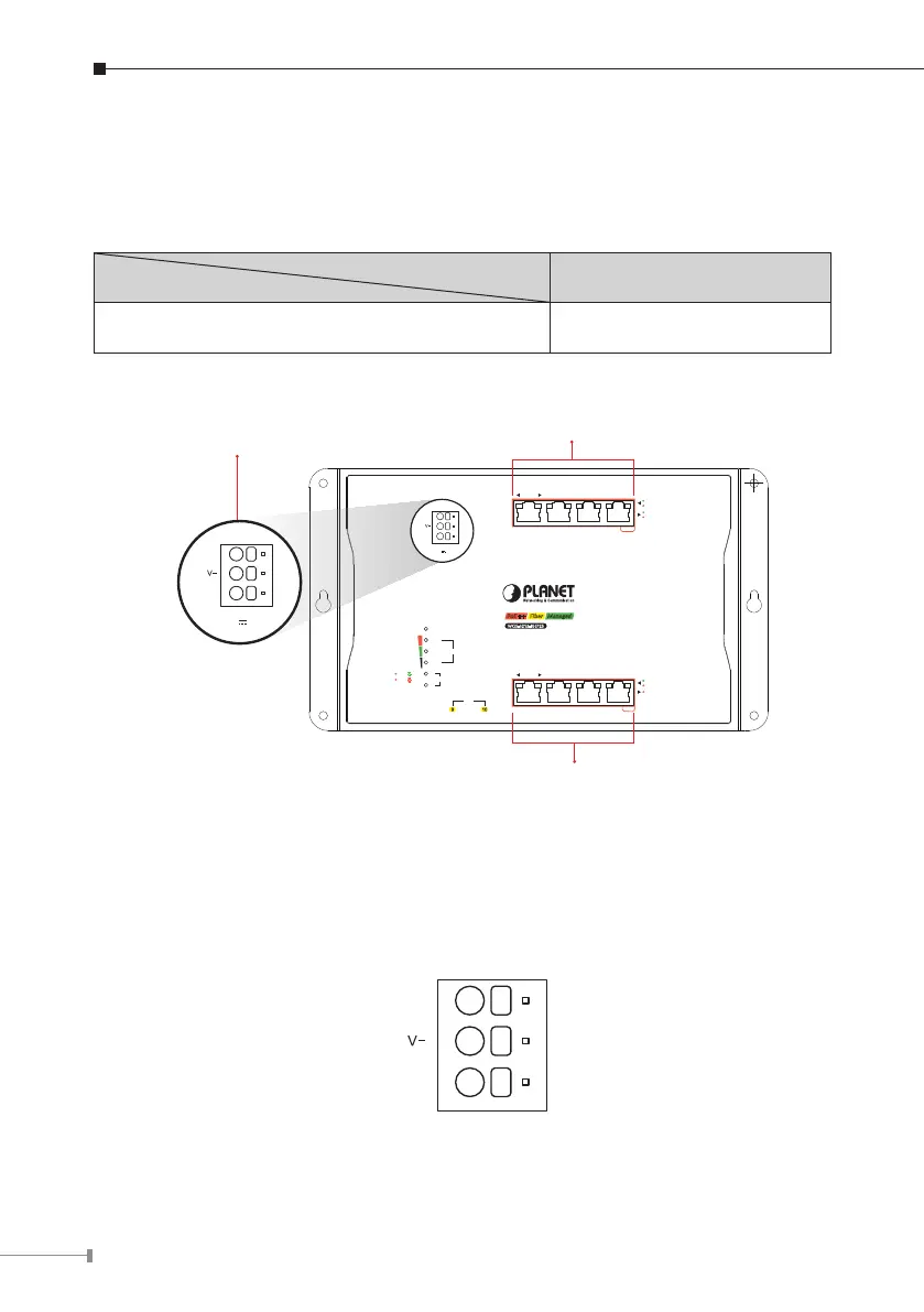
4.1 Terminal Block Connector Pinout
TheFrontPaneloftheWall-mountManagedSwitchconsistsofoneterminal block
connector within 3 contacts. Please follow the steps below to insert the power
wire.
V+
Insertpositive/negativeDCpowerwiresintoContactsV+andV-forPower.
 Loading...