42
A more advanced search can be done for any faults, by access-
ing the front rack board and examining the diagnostic LEDs
provided.
The purpose of this board is to allow the operator to regulate
and interact with the machine, and determines all the functions
necessary for it to function, and for the cut to be executed.
The operator interface is in the form of a membrane keyboard
on the front panel, which included diagnostic / functional LED’s
for the machine, and the operating buttons for selecting the cut-
ting mode and activating the air flow test.
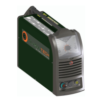
To be able to access the control board, proceed as follows
(Fig. S):
• Unscrew the 4 screws that fix the front rack panel.
•
The control board is fixed to the front rack, removed previ-
ously.
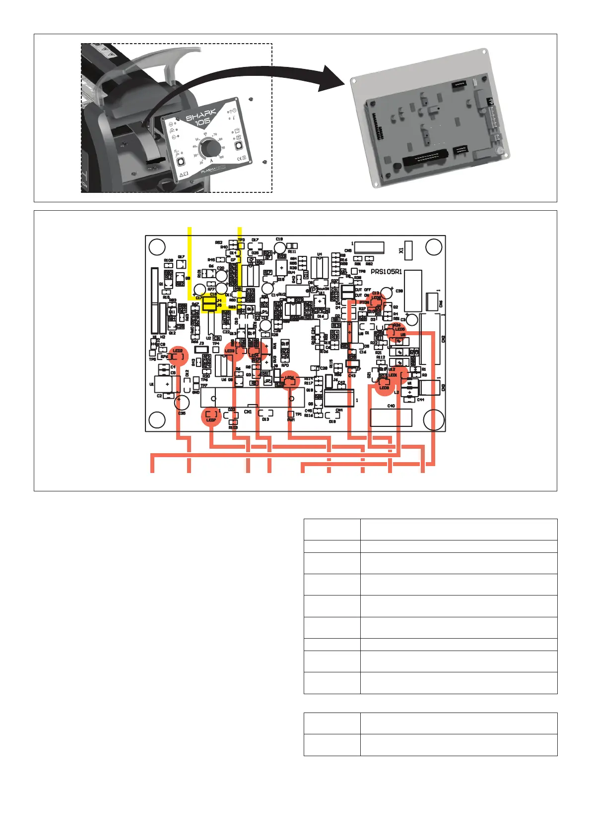
Figure T shows the layout of the front control rack board, high-
lighting the diagnostic LEDs and main trimmers fitted.
FIG. S
List of LEDs
LED1 Green LED, on when the TORCH BUTTON is
pushed.
LED2 Green LED, on when the +24 voltage is on.
LED3
Green LED, on when the inverter board is in an
OVER VOLTAGE state.
LED4 Green LED, on when the inverter board is in an
UNDER VOLTAGE state.
LED5 Green LED, one when the ARC TRANSFERRED
signal is active.
LED6 Green LED, on when the air solenoid valve is
activated.
LED7 Green LED, on when the fan is switched on.
LED8 Green LED, on when the torch button signal is
recognised by the board.
LED9 Green LED, on when the safety optical unit
PT(U12) is switched off (PT OFF).
List of JUMPERS
JP1 When inserted, on switching on the machine will
be in SOLID CUT mode.
JP2 When inserted, on switching on the machine will
be in MESH CUT mode.
J4 J5
LED1 LED2 LED3 LED4 LED5 LED6 LED7 LED8 LED9
FIG. T