6
Usage norms
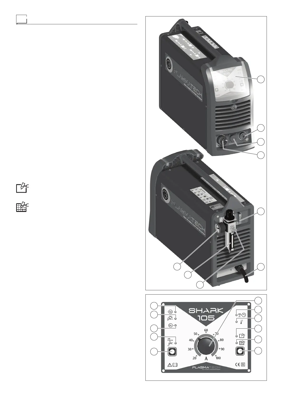
COMMAND AND CONTROL DEVICES (Fig. A)
Pos. 1 Control panel (Fig. B).
Pos. 2 Snap-in connector for ground line.
Pos. 3 Connector, 14 pole, for CNC control interface (option-
al extra).
Pos. 4 Centralised torch attachment.
Pos. 5 Power supply switch.
Pos. 6 Cutting machine power supply cable.
Pos. 7 Fast coupling to connect compressed air tube.
Pos. 8 Filter and cutting air pressure regulator. The air filter
automatically expels impurities.
Pos. 9 Pressure gauge for reading cutting air pressure.
CONTROL PANEL (Fig. B)
Pos. 1 Cutting current adjustment knob.
Pos. 2 Yellow LED: signals lack of compressed air. It lights
up when air pressure is below the set value.
Pos. 3 Yellow LED: signals intervention of overheat cutoff.
This LED shines to indi cate that the overheating pro-
tection has cut in because the work cycle is not being
followed. After several minutes the overheat cut-off
rearms automatically (and the yellow LED turns itself
off) and the welder is ready for use again.
Pos. 4 Green selection LED for full cut mode. When this LED
is switched on, it means that the operator has set the
cutting mode for solid material.
Pos. 5 Green selection LED for mesh cutting mode. When
this LED is switched on, it means that the operator
has set the cutting mode for mesh material.
Pos. 6 Cutting mode selection button.
This can be used to select one of the 2 cutting modes,
as indicated by the corresponding LED that switches
on:
•
Solid material mode (when the torch button is
pushed, when the operator goes out of the work-
piece during cutting, the arc switches off automati-
cally).
•
Mesh material mode (when the torch button is
pushed, when the operator goes out of the work-
piece during cutting, the pilot arc ignites again au-
tomatically, to allow cutting to continue).
Pos. 7 Compressed air button.
When this button is pushed and released, the cutting
air valve opens, allowing the operator to regulate the
compressed air pressure, using the filter / regulator
knob (Pos. 8, Fig. A) located on the back panel.
The pressure gauge (Pos. 9, Fig. A) provides a read-
ing for the cutting air pressure.
The operation is terminated manually by pushing the
cutting torch button, or automatically after a time of
about one minute.
Pos. 8 Green compressed air button LED
When this LED is switched on, this means the oper-
ator is doing the compressed air test.
Pos. 9 Red inverter switch on indication LED. The machine
is “on” and ready for the cutting operation.
Pos. 10 Red LED: signals activation of torch button. When
the torch button is pushed, the LED switches on and
the machine checks correct functioning of the plas-
ma torch connection.
Pos. 11 Green LED - power supply on. When on the system
is powered and ready for use.
1
2
5
6
8
9
3
4
FIG. A
6
5
4
3
2
1
10
9
8
7
11
FIG. B