44
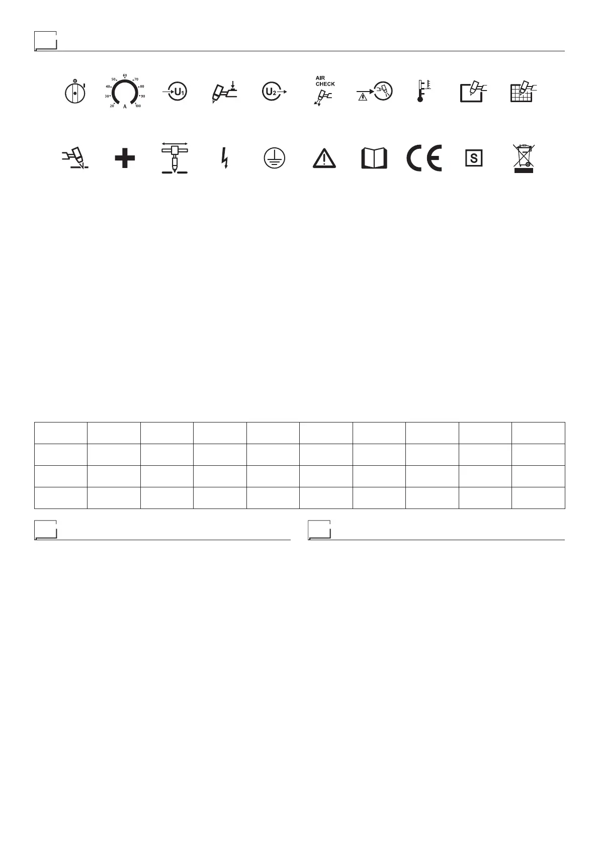
Meaning of graphic symbols on machine
11
19
AIR
17
18
12
13
15
14
ON
16
20
•1 Main equipment switch •2 Cutting current scale potentiometer •3 Green LED: signals power ON •4 Red LED: signals activation of torch button •5 Red
LED to indicate that the inverter is activated and the machine is working •6 Green LED, air test activated •7 Yellow LED: signals lack of compressed air
•8 Yellow LED for overheat cutoff •9 Green LED, solid material cutting mode •10 Green LED, mesh material cutting mode •11 Centralised plasma torch
connection connector •12 Positive earth cable connection polarity •13 Connector for CNC control •14 Dangerous voltage •15 Grounding protection •16
Warning! •17 Before using the equipment you should carefully read the instructions included in this manual •18 Product suitable for free circulation in the
European Community •19 System for use in environments with increased risk of electrocution •20 Special disposal
Key to the electrical diagram
•1 CNC controller •2 EMC condenser •3 Plasma torch connector, machine
side •4 Secondary circuit diode module •5 Plasma torch electrode •6 Air
solenoid valve •7 EMC filter •8 Regulator filter •9 Mains switch •10 Induct-
ance •11 Pressure gauge •12 Primary circuit IGBT module •13 Fan motor
•14 Current potentiometer •15 Earth clamp •16 Pressure switch •17 Plas-
ma torch button •18 Pilot arc IGBT circuit •19 Front panel membrane key-
board •20 Primary circuit rectifier •21 Voltage divider resistor •22 Secondary
circuit snubber resistor •23 Power supply board •24 Rack panel board •25
Primary Inverter PCB •26 Exhaust •27 Plasma torch safety sensor •28
Auxiliary transformer •29 Inductor thermostat (SHARK 105) •30 Primary
circuit thermistor •31 Secondary circuit thermostat •32 Plasma torch noz-
zle •33 Main transformer •34 Plasma torch •35 Secondary circuit varistor
Colour key
AN Orange-Black
Ar Orange
Az Sky Blue
Bc White
Bl Blue
BN White-Black
Gg Grey
Gl Yellow
GV Yellow-Green
Mr Brown
Nr Black
RN Red-Black
Ro Pink
Rs Red
Vd Green
Vl Violet
•1 •2 •3 •4 •5 •6 •7 •8 •9 •10
CNC CP CT D1-2 EL EVG FE FR IL L
•11 •12 •13 •14 •15 •16 •17 •18 •19 •20
M MI MV P PM PR PT Q1 RF RP
•21 •22 •23 •24 •25 •26 •27 •28 •29 •30
RV RSN S-AL S-INT DIG S-INV SL ST TA THI THP
•31 •32 •33 •34 •35
THS TIP TP TPL V