Instruction book
9828 0931 61 13
2.2 Air system
Air flow diagram
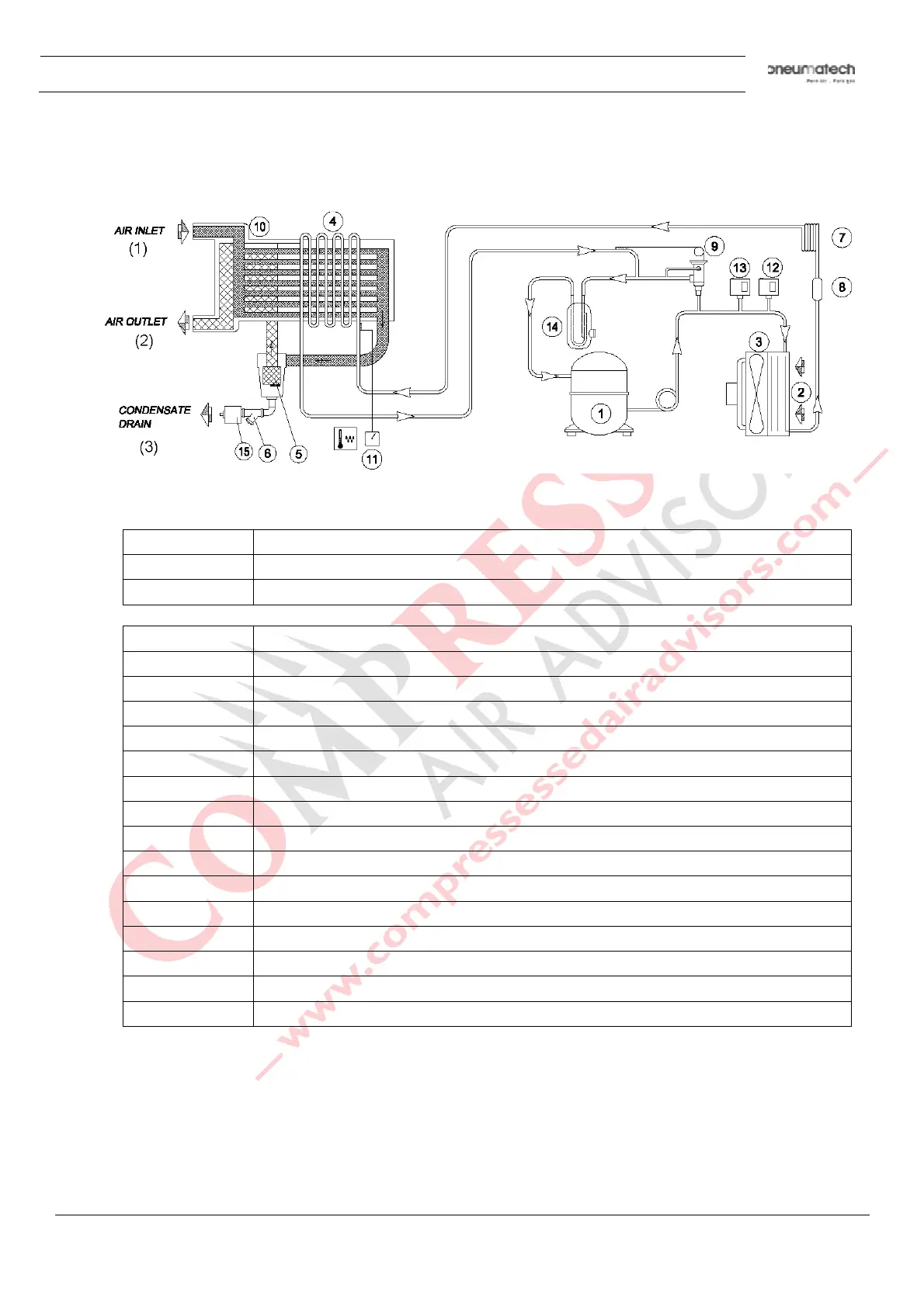
Text on figure:
(1) Air inlet
(2) Air outlet
(3) Condensate drain
Reference Name
1 Refrigerant compressor
2 Condenser
3 Motor and fan
4 Evaporator
5 Condensate separator
6 Impurity trap
7 Expansion capillary tube
8 Refrigerant filter
9 Hot gas by-pass valve
10 Air/air heat exchanger
11 Digital controller
12 Fan control switch
13 High pressure shut-down switch
14 Liquid separator
15 Automatic condensate drain
Description
Compressed air enters heat exchanger (10) and is pre-cooled by the outgoing, cold, dried air. Water in
the incoming compressed air starts to condense. The air then flows through heat exchanger/evaporator
(4) where the refrigerant evaporates causing the air to be cooled further to close to the evaporating
temperature of the refrigerant. This results in further condensation. The cold air then flows through
separator (5) where all the condensate is separated from the air. The condensate is automatically
drained.