Instruction book
9828 0931 61 15
Description
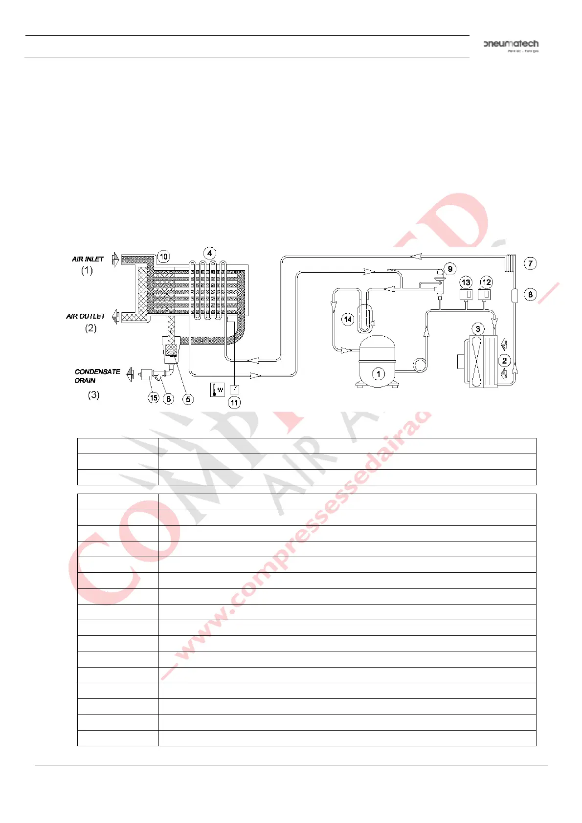
Compressor (1) delivers hot, high-pressure refrigerant gas which flows through condenser (2) where
most of the refrigerant condenses.
The liquid flows through liquid refrigerant dryer/filter (8) to capillary tube (7). The refrigerant leaves the
capillary tube at evaporating pressure.
The refrigerant enters evaporator (4) where it withdraws heat from the compressed air by further
evaporation at constant pressure. The heated refrigerant leaves the evaporator and is sucked in by the
compressor (1).
2.4 Automatic regulation system
Air flow diagram
T
ext on figure:
(1) Air inlet
(2) Air outlet
(3) Condensate drain
Reference Name
1 Refrigerant compressor
2 Condenser
3 Motor and fan
4 Evaporator
5 Condensate separator
6 Impurity trap
7 Expansion capillary tube
8 Refrigerant filter
9 Hot gas by-pass valve
10 Air/air heat exchanger
11 Digital controller
12 Fan control switch
13 High pressure shut-down switch
14 Liquid separator
15 Automatic condensate drain