Instruction book
14 9828 0931 61
The cold, dried air flows through heat exchanger (10) where it is warmed up by the incoming air to
approx. 10˚C (18˚F) below the incoming air temperature.
Condensation in the air net cannot occur unless the air is cooled below the pressure dewpoint indicated
by the digital controller (11).
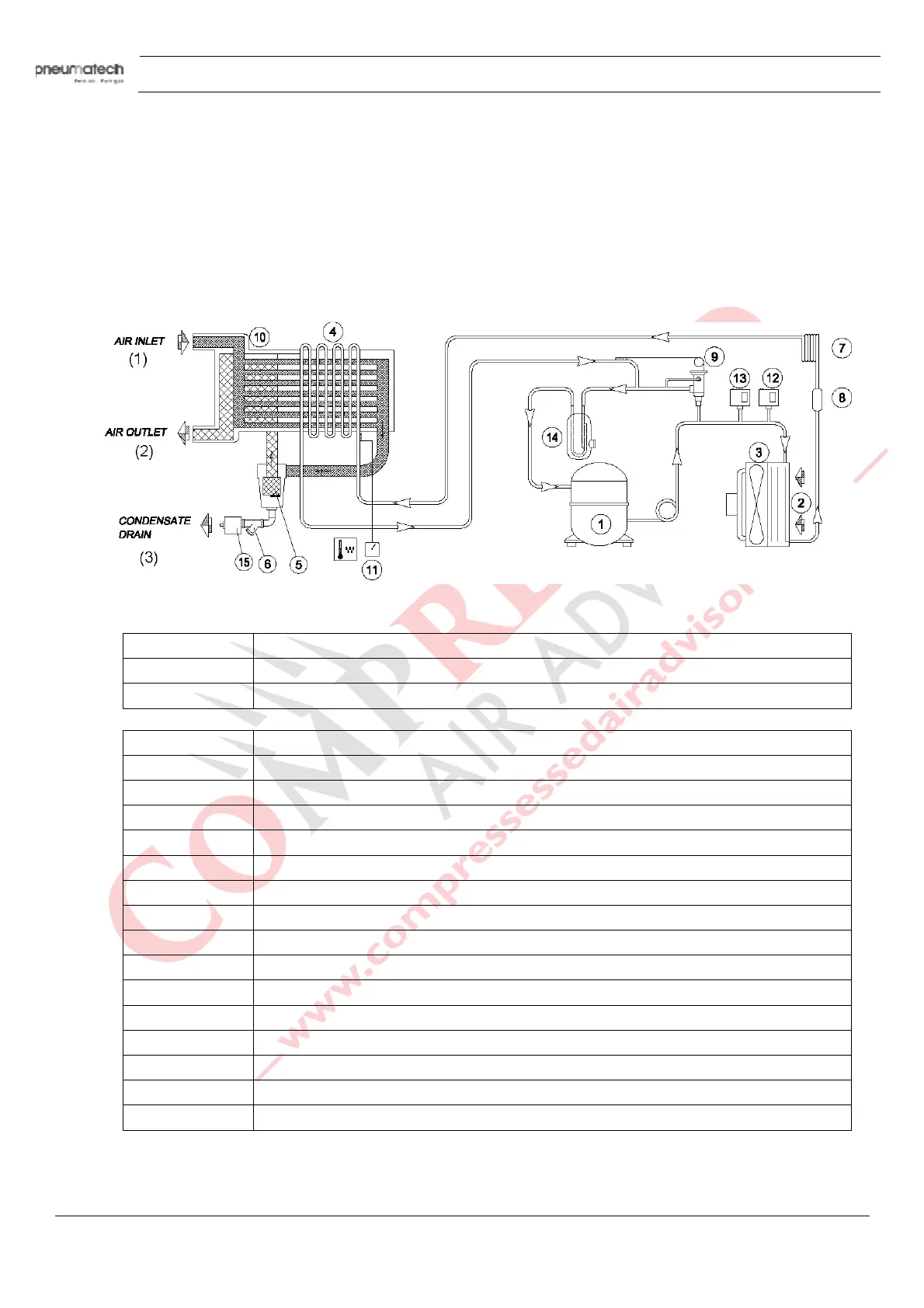
2.3 Refrigeration system
Refrigerant flow diagram
T
ext on figure:
(1) Air inlet
(2) Air outlet
(3) Condensate drain
Reference N
ame
1 Refrigerant compressor
2 Condenser
3 Motor and fan
4 Evaporator
5 Condensate separator
6 Impurity trap
7 Expansion capillary tube
8 Refrigerant filter
9 Hot gas by-pass valve
10 Air/air heat exchanger
11 Digital controller
12 Fan control switch
13 High pressure shut-down switch
14 Liquid separator
15 Automatic condensate drain