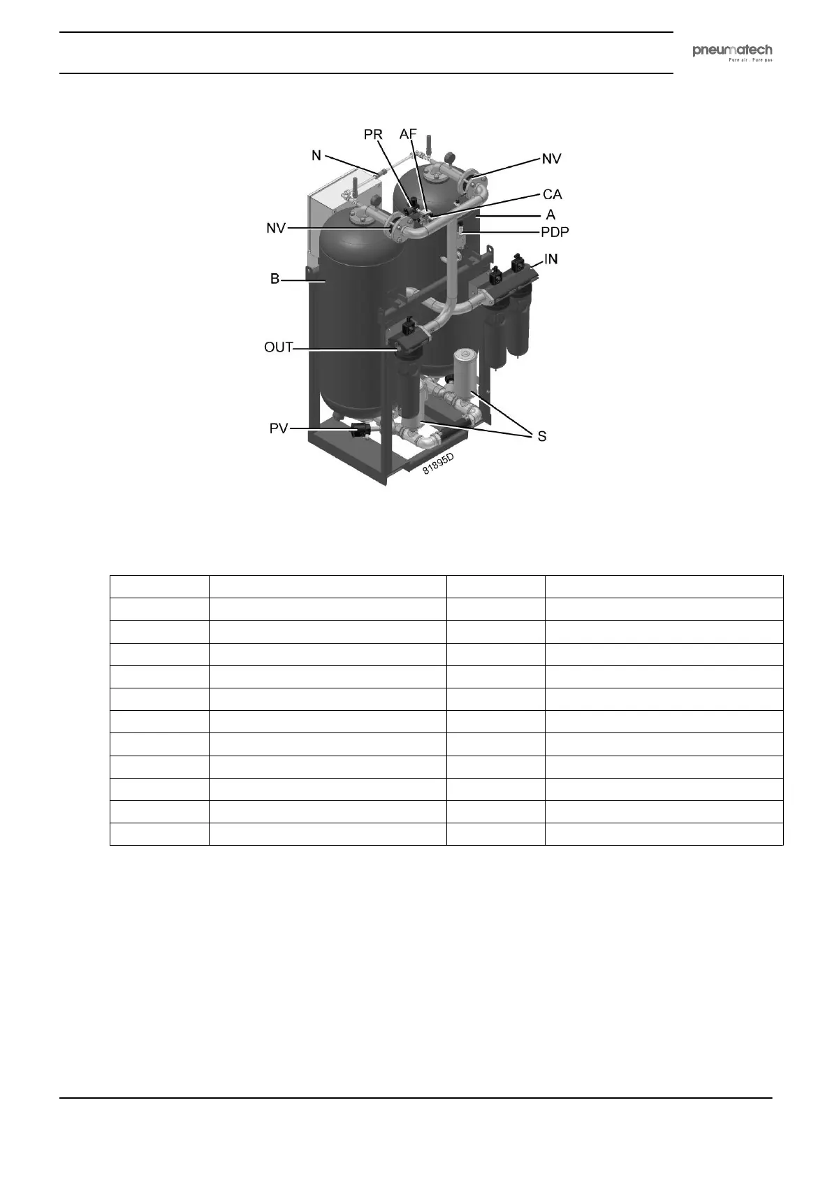
Rear view PH 230 HE up to PH 635 HE
Reference Designation Reference Designation
A Tower A 1 Control panel
B Tower B 2 Purelogic™ controller
IN Dryer inlet 3 Cubicle
OUT Dryer outlet SV Solenoid valves
IV Inlet valve N Nozzle for regeneration air
PA Pneumatic actuator P1 Pressure gauge, tower A
PV Pneumatic valve P2 Pressure gauge, tower B
S Silencer AF Air filter
NV Non-return valve CA Control air valve
PR Pressure regulator (232 psi version) PDP PDP sensor (if installed)
P01 Pressure sensor P02 Pressure sensor
Control panel
The dryer is controlled by a Purelogic
TM
controller. Consult the dedicated chapter for a complete
description of the controller functions.
Safety valve
If no fire extinguishing system is present close to the dryer, safety valves must be installed on the vessels of
the dryer in order to relieve the overpressure in the vessel because of fire in the neighbourhood of the dryer.
Instruction book
2920 1891 00 9