FUEL INJECTION / IGNITION / EXHAUST SYSTEMS
5.12
2004 Four Stroke PWC Service Manual
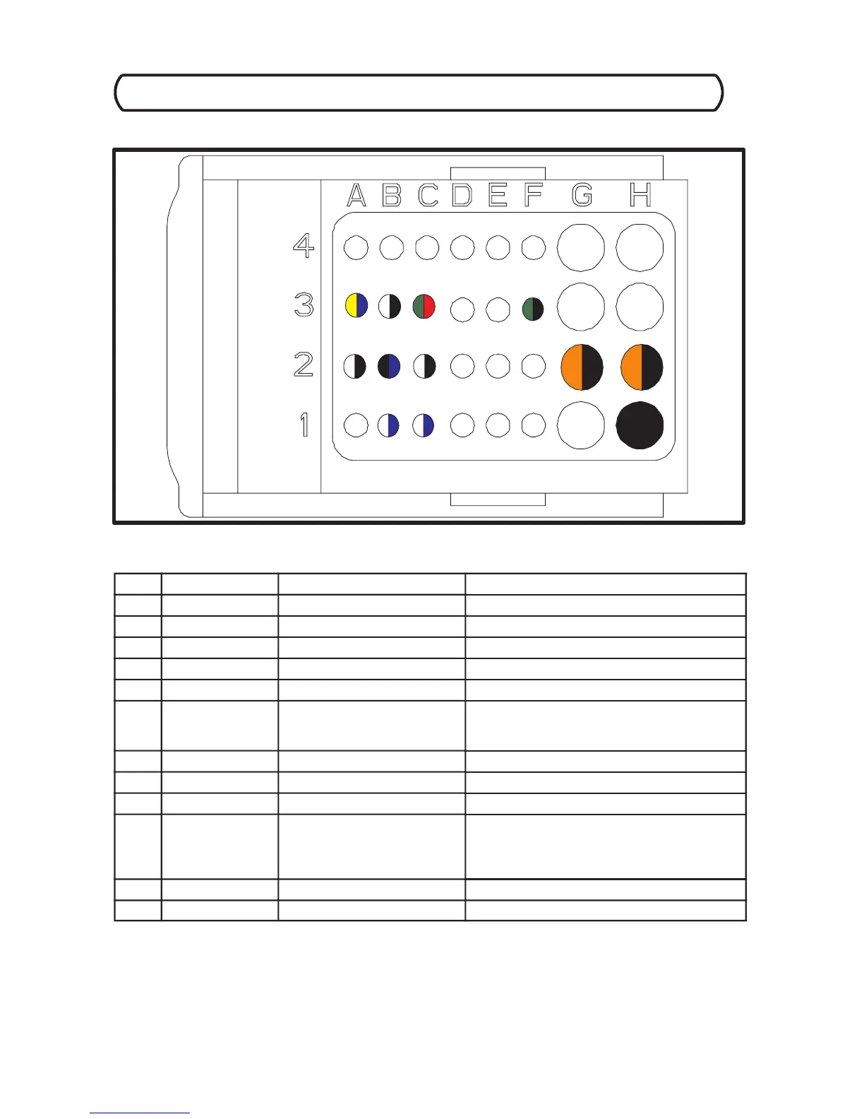
ECU C100 Harness Connector (Grey Color Code)
ECU C100 Harness Connector Interface Description (As viewed from terminal side.)
PIN WIRE COLOR PIN FUNCTION SENSOR / SENSOR PIN #
H1 BLACK Electronic Ground Splice 8
C1 BLUE/WHT Manifold Pressure Signal Manifold Pressure Sensor / 4
B1 BLUE/WHT Engine Speed Sensor Signal Engine Speed Sensor / 1
H2 BLK/OR Fuel Injector Output Signal PTO Fuel Injector / 2
G2 BLK/OR Fuel Injector Output Signal MAG Fuel Injector / 2
C2 BLK/WHT Sensor Reference Ground (Splice 4)
Manifold Pressure Sensor / 1
Boost Pressure Intake Temp. Sensor / 1
B2 BLU/BLK Engine Speed Sensor Signal Engine Speed Sensor / 2
A2 BLK/WHT Sensor Reference Ground Cam Phase Sensor / 1
F3 BLK/GRN Fuel Pump Relay Signal Main Relay / 7
C3 RED/GRN 5 Volt Reference Output
Signal
(Splice 5)
Cam Phase Sensor / 3
Manifold Pressure Sensor / 3
Boost Pressure -- Intake Temp. Sensor / 3
B3 BLK/WHT O2 Reference Ground Lambda Sensor / 3
A3 BLU/YEL O2 Signal Input Lambda Sensor / 4
 Loading...