FUEL INJECTION / IGNITION / EXHAUST SYSTEMS
5.132004 Four Stroke PWC Service Manual
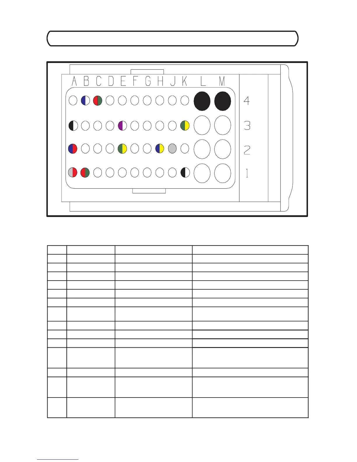
ECU C200 Harness Connector (Brown Color Code)
ECU C200 Harness Connector Interface Description (As viewed from terminal side.)
PIN WIRE COLOR PIN FUNCTION SENSOR / SENSOR PIN #
B4 BLU/WHT Ignition Switch Input System Interface Box / C
C4 GRN/RED Check Engine MIL Lamp Engine -- Chassis Connector / G
L4 BLACK Electronic Ground Splice 7
M4 BLACK Fuel Injection Ground Splice 8
A3 BLK/WHT Engine Speed Sensor Ground Engine Speed Sensor / 3
E3 PUR/WHT ESP Signal Input Engine -- Chassis Connector / B
K3 GRN/YEL Engine High Temp. MIL
Output
Engine -- Chassis Connector / H
A2 BLU/RED Pedal Position 2 Input PPU Interface Box / A
E2 GRN/YEL Reverse Switch Signal Input System Interface Box / B
H2 BLU/YEL Diagnostic K--Line Diagnostic Connector / A
J2 GREY Engine Speed Signal (TACH.)
Output
(Splice 12)
System Interface Box / G
Engine -- Chassis Connector / K
A1 GRY/RED Pedal Position 1 Input PPU Interface Box / C
B1 RED/GRN Pedal Position Supply Voltage (Splice 11)
Pedal Position Unit / 3, 6
PPU Interface Box / B
K1 BLK/WHT Pedal Position Reference
Ground
(Splice 10)
Pedal Position Unit / 4, 5
PPU Interface Box / E
 Loading...