FUEL INJECTION / IGNITION / EXHAUST SYSTEMS
5.14
2004 Four Stroke PWC Service Manual
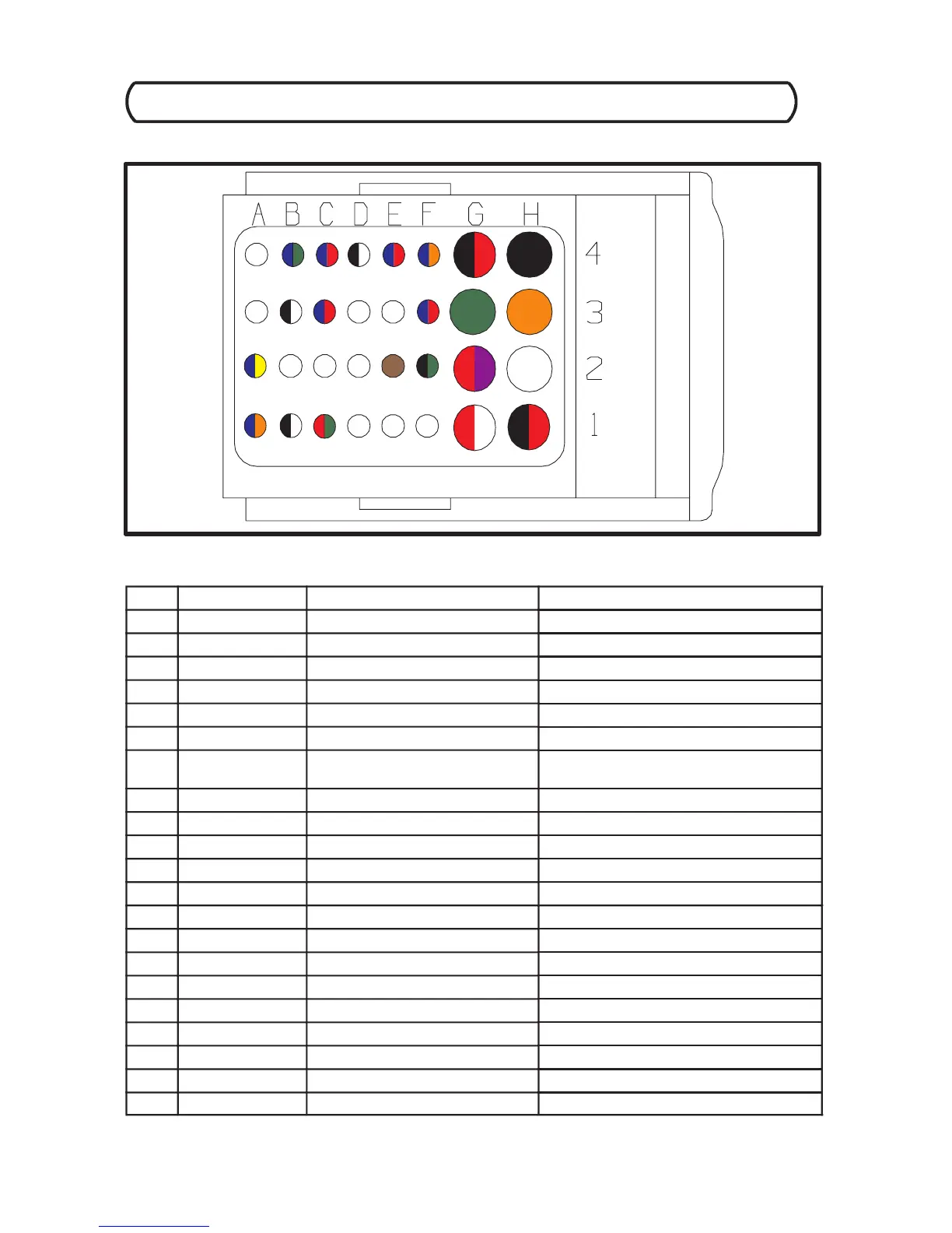
ECU C300 Harness Connector (Black Color Code)
ECU C300 Harness Connector Interface Description (As viewed from terminal side.)
PIN WIRE COLOR PIN FUNCTION SENSOR / SENSOR PIN #
B4 BLU/GRN Throttle Position 2 Electronic Throttle Body / 5
C4 BLU/RED Temp. Switch Input Temp.Switch/A
D4 BLK/WHT Sensor Reference Ground Engine Temp. Sensor / 2
E4 BLU/RED Engine Temp. Signal Input Engine Temp. Sensor / 1
F4 BLU/OR Boost Pressure Signal Boost Pressure -- Intake Temp. Sensor / 4
G4 BLK/RED Sensor Reference Ground W astegate Solenoid / 1
H4 BLACK Ignition Ground (Splice 6)
Ignition Coils / 2
B3 BLK/WHT Knock Sensor Ground Knock Sensor / 2
C3 BLU/RED Knock Sensor Signal Knock Sensor / 1
F3 BLU/RED Cam Phase Sensor Signal Cam Phase Sensor / 2
G3 GREEN Ignition Driver 1 PTO Ignition Primary / 1
H3 ORANGE Ignition Driver 2 MAG Ignition Primary / 1
A2 BLU/YEL Intake Air Temp. Signal Boost Pressure -- Intake Temp. Sensor / 2
E2 BROWN O2 Heating Supply Lambda Sensor / 2
F2 BLK/GRN Main Relay Output Main Relay / 10
G2 RED/PUR Switched Battery Supply Input Main Relay / 2
A1 BLU/OR Throttle Position 1 Input Electronic Throttle Body / 6
B1 BLK/WHT Throttle Position Ref. Ground Electronic Throttle Body / 2
C1 RED/GRN Throttle Position Supply Voltage Electronic Throttle Body / 3
G1 RED/WHT Throttle Plate Positive Voltage Electronic Throttle Body / 4
H1 BLK/RED Throttle Plate Negative Voltage Electronic Throttle Body / 1
 Loading...