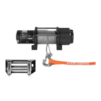
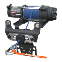
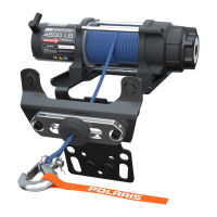
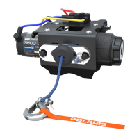
This document describes the installation and operation of the Polaris PRO HD 4500 Winch Kit, designed exclusively for Polaris vehicles. The kit includes the winch assembly, various cables (yellow, blue, black, red), a latch hook, a control box, rope, a wireless remote kit, a contactor, an autostop fairlead, winch and fairlead mount brackets, a rubber stop magnet, and various screws and nuts for installation. A separate power cable kit is required for most models, with the exception of the MY17 RZR Turbo, which comes pre-wired for winch installation.
Function Description
The Polaris PRO HD 4500 Winch Kit provides a powerful winching solution for Polaris vehicles, enabling users to pull loads and recover their vehicle or other objects. Key components work together to ensure safe and efficient operation. The winch assembly, powered by the vehicle's electrical system, spools and unspools the rope. The contactor acts as a relay, controlling the flow of power to the winch. The control box manages the winch's functions, while the wireless remote allows for remote operation, enhancing safety by enabling the user to stand clear of the vehicle during winching. The autostop fairlead and rubber stop magnet are integral to the Autostop system, which prevents over-tightening of the rope and potential damage to the winch.
Usage Features
Installation:
The installation process involves several preparatory steps, including shifting the vehicle into "PARK," turning off the ignition, removing the driver's seat, disconnecting the battery (negative cable first), removing the hood, shift lever cap, center console, plastic winch cover, front fascia, and headlight connectors. Once the vehicle is prepared, the power cable kit (if required) is routed from the battery to the bus bar terminals, ensuring not to connect them at this stage.
The winch mounting bracket is then installed onto the chassis and front suspension brackets using screws and nuts, torqued to specification. The winch assembly is slid onto the mounting bracket and secured with screws, also torqued to specification. The blue and yellow winch cables are connected to their corresponding color terminals on the winch assembly. The autostop fairlead is installed onto the fairlead mounting bracket.
The winch rope is fed through the fairlead mounting bracket, autostop fairlead, and rubber stop, with the winch hook installed onto the rope. A helpful hint suggests attaching a plastic cable tie to the end of the rope to feed it through the rubber stop, using a mild lubricant if needed.
The contactor is installed onto the firewall using screws, tightened until snug but not overtightened. The blue, yellow, red, and black cables are connected to the contactor terminals and torqued to specification. Power wires from the control box are routed to the bus bar, connecting the red positive wire to the orange, keyed power terminal and the black negative wire to the black (ground) terminal. All remaining wires are secured with cable ties.
The wireless remote receiver is mounted onto the chassis, and its electrical connectors are connected. Its power wires are routed to the bus bar, connecting the red positive wire to the keyed power terminal and the black negative cable to the ground terminal. All remaining power wires are secured.
Wireless Remote Operation:
The wireless remote holder can be installed in a desired location on the vehicle. To use the remote, hold the "On/Off" button for three seconds until the LED light turns on. The remote will operate the winch if the vehicle is on and the winch is receiving power. The remote automatically turns off after 30 seconds of inactivity and needs to be turned back on for subsequent use. To manually turn off the remote, hold the "On/Off" button for three seconds until the LED light turns off.
Autostop Operation:
The Autostop system is designed to prevent damage from over-tightening the rope. It functions when the black rubber puck nears the aluminum fairlead, triggering sensors that prevent the winch from pulling in the rope further. It is important to note that this system is a secondary preventive measure, and the operator is always responsible for proper winch usage.
Gear Selection:
The winch features three gear settings: High, Neutral, and Low.
- Neutral (N): The "N" marking shows through the cutout window on the shift knob.
- Low (L): To shift into low gear, rotate the gear shifting knob counter-clockwise until the "L" marking shows through the cutout window. Low gear is the standard operating mode.
- High (H) / Rapid Recovery: To shift into high gear, rotate the gear shifting knob clockwise until the "H" marking shows through the cutout window. High gear is for rapid recovery of the winch rope only and should not be used under load. It significantly reduces the time to rewind the rope after use, operating approximately five times faster than standard operation. Caution should be exercised, and the winch should always be reset to "Low" gear after using Rapid Recovery to avoid unexpected speed.
Important Safety Note for Gear Shifting:
Attempting to shift the winch while the rope is under tension is dangerous and can result in injuries or death. Always ensure the winch rope is not under tension before shifting between gears.
Maintenance Features
Troubleshooting:
The manual provides a comprehensive troubleshooting guide for common issues:
- Dead Vehicle Battery: Check power wire connections and ensure no current draw when the vehicle is off. Rewire if necessary.
- Winch Will Not Operate:
- Contactor not receiving power: Turn the vehicle key on.
- Wireless remote not powered on: Turn the wireless remote on.
- Connections between components not in proper order: Check connections. Ensure the handlebar switch connection is directly connected to the contactor.
- Keyed power circuit not properly powered: Check the fusebox for the 10A accessory circuit and voltage in orange wires from the main harness.
- Winch Operates in One Direction Only:
- Autostop fairlead not connected properly: Check connections. If the winch operates only outward, ensure the black rubber puck is not touching the aluminum fairlead. If it operates inward even when the puck is touching the fairlead, check connections of the Autostop control box. If it operates inward but not outward, check wire colors at connectors for proper matching.
- Winch Makes Noise But Rope Does Not Move:
- Winch not in proper gear: Rotate the gear knob fully into L or H, then recheck.
- Contactor powered, but not winch: If a clicking sound is heard but no winch movement, check connections between the winch and the contactor. If the winch makes noise but doesn't move, check if the winch is in gear. If it's in gear and still doesn't move, a dealer inspection is recommended.
- Winch Operates Too Slowly:
- Winch in wrong gear: Rotate the gear knob into the proper gear, then recheck.
- Winch improperly loaded: Low gear is inherently slow. In High (Rapid Recovery) gear, the winch operates quickly but can slow down if there's a load on the rope or if the rope is bound up. Check that the winch is clear and the rope is not bound up or under load.
- Winch Will Not Change Gears:
- Rope is still under load: Gears are designed to be hard to shift under load to prevent accidental operation. Ensure the rope has no load or tension and is not bunched up. Operate the winch for a short period, then attempt to shift again.
Final Inspection:
After installation, confirm all wiring is correct, ensure no exposed wires or terminals, and secure all loose wires away from moving parts and heat sources. Verify that the Autostop is functioning properly.
Reinstallation:
The final steps involve reinstalling the front fascia, headlight connectors, center console, shift knob and lever cap, hood, main vehicle battery cables, power cable kit cables, and finally, the seat.