TRANSMISSION
8.2
TORQUE SPECIFICATIONS
Transmission Case Bolts 20 ft. lbs. (27 Nm).....
Bell Crank Nut 15 ft. lbs. (20 Nm)..............
T ransmission Drain Plug 14 ft. lbs. (19 Nm).....
T ransmission Fill Plug 14 ft. lbs. (19 Nm)........
T ransmission Mounting Bolts 25 ft. lbs. (35 Nm)..
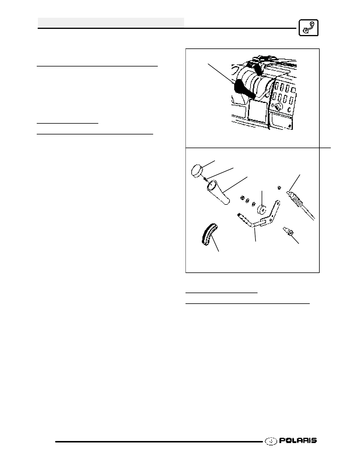
SHIFT LEVER
REMOVAL/INSTALLA
TION
1. Disconnect linkage cable from shifter.
2. Remove one bolt attaching gear selector mount to
machine frame.
3. Remove the cover and remove screw. Pull off the
shifter knob.
4. Lift gear selector out of mounting bracket and
away from frame.
5. Repeat the steps in reverse order to install the
gear selector .
Cover
Screw
Shifter Knob
Grommet
Shifter
Cable
Bolt
Bearing
Shift Lever Location
Shift Lever
Shift Lever Breakdown
SHIFT LINKAGE
INSPECTION/ADJUSTMENT
Linkage rod adjustment is necessary when symptoms
include:
S No All Wheel Drive light
S Noise on deceleration
S Inability to engage a gear
S Excessive gear clash (noise)
S Shift selectors moving out of desired
range
NOTE: Remove necessary components to gain
access to shift linkage cable ends (i.e. exhaust heat
shield, exhaust pipe, etc.).
 Loading...