4 – LCD area, which indicates the hours and the minutes of the current time in DER
indication mode or the time of averaging DER values (in seconds) in DER indication mode,
DE accumulation time in DE indication mode in hours, the year of production in the
dosimeter’s number indication mode;
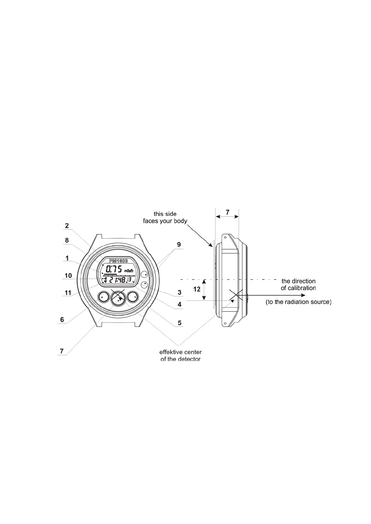
5 – the SET button (setting) for switching on PC communication mode, entering the set
mode and exiting it (see item 2.1.6);
6 – the MODE button for selecting the dosimeter’s indication mode (DER, DE, the
dosimeter’s number, PC communication, alarm clock, timer, stop-watch, clock-calendar);
7 – the LIGHT button for switching on LCD backlight;
8 – LCD;
9 – IR-transceiver window;
10 – alarm turn-on symbol;
11 – alarm clock turn-on symbol.
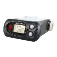
A direction of calibration and the detector effective center relative to which the factory
calibration is performed are shown on Figure 1.2. The total surface density of the walls
surrounding the detector is 1 g/cm
2
that provides the detector shielding from the
background beta radiation.
Figure 1.2 – General overview of the dosimeter