1.4 Design and principle of operation
1.4.1 Design
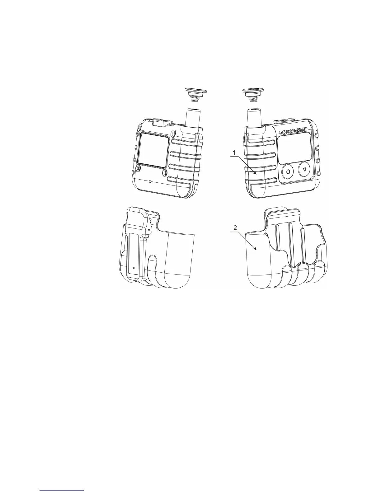
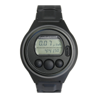
The dosimeter is shown in Figure 1.1.
1 – dosimeter;
2 – holder with clip.
Figure 1.1 – Physical configuration of the dosimeter
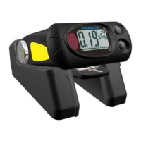
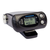
The overall dimensions, direction of calibration and geometrical center of the dosimeter’s
detector are shown in Figure 1.2.
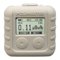
The body of the dosimeter is made of a shockproof plastic. The front panel of the dosimeter
(Figure 1.2) contains a matrix LCD and two control buttons (2, 3).
Mini USB connector (5) (closed with plug), light emitting diode of visual alarm (6) and
sound alarm outlet (4) are on top of the dosimeter. The label with the model number and serial
number are on the back side of the dosimeter.
The cable from the delivery kit of the dosimeter is used to connect the dosimeter to a
computer.