Page 7 of 13
©2010 Polycom, Inc. All rights reserved. Polycom and the Polycom logo design and Polycom HDX are registered trademarks of Polycom, Inc.
All other trademarks are the property of their respective owners. Information is subject to change without notice.
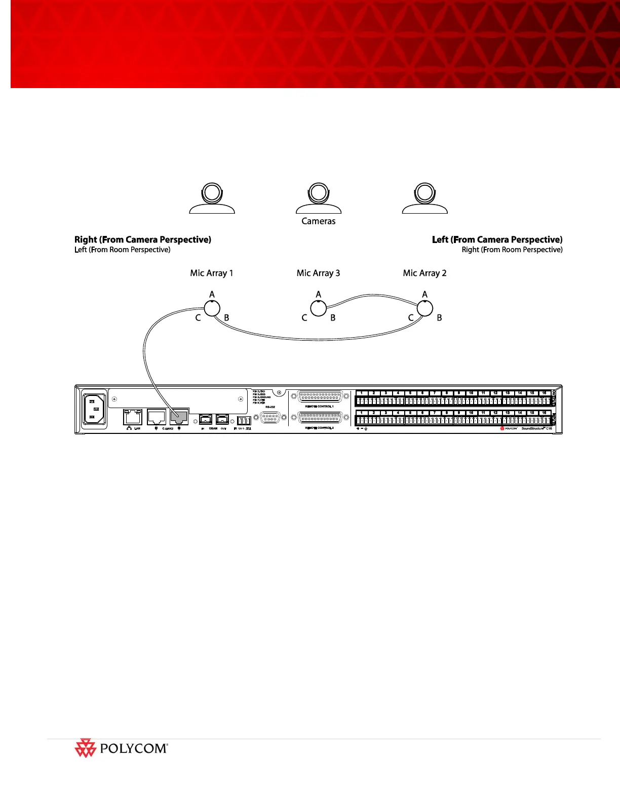
pointed directly towards the loudspeakers and displays and are not used in conferencing. To delete
these elements, use the Edit Channels control to delete the “A” element of each of these microphone
arrays from the SoundStructure configuration file. Once the “A” elements have been removed, only two
microphone elements per microphone array remain for a total of six microphones. This means that any
SoundStructure C-series product, including the SoundStructure C8, may be integrated with the ATX
system and still support the three “two-element” microphone arrays.
Figure 8. Microphone array orientation and sequential positioning and element numbering.
Once the microphones are properly positioned and daisy-chained, the microphones will be used in the
matrix as described next.
5.2 SoundStructure Matrix Settings
SoundStructure Studio can be used to view and modify SoundStructure configuration files. This section
describes the matrix settings for the Conference Link method of integration between the SoundStructure
device and the HDX 8000 codec. See the online training streams [5] or the SoundStructure Design Guide
[6] for more information about creating a SoundStructure configuration file.
The matrix settings are shown in the following figure and the highlighted values are described in detail
below.
1. The six microphone array elements (two elements remain per microphone array) belong to the
“Mics” group and have a fader value of 6dB applied to ensure the microphone levels are in the
proper range. While the names of the microphone channels in this example were chosen to help
understand the physical position of the individual microphone elements, any valid name may be
used.
2. The echo cancelled Polycom Microphone Array elements are panned to the left and right to the
“Mics_Stereo_Panned” submix to create an immersive audio experience at the remote site.