Installing The SoundStructure C16, C12, C8, And SR12
2 - 17
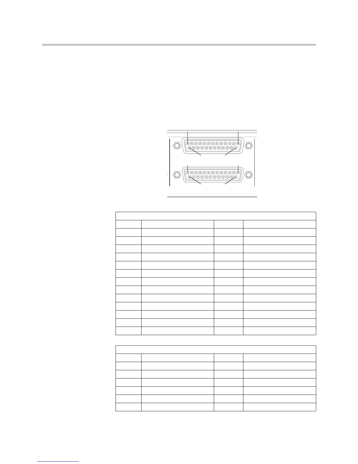
Each Remote Control connector includes eleven logic inputs, eleven logic
outputs, an analog gain control input, a +5 V supply capable of providing up
to 500 mA, and a logic ground. Internal to the SoundStructure device is a fuse
that will trigger if the current draw on Pin 1 exceeds 500 mA. The fuse will
reset itself once the excessive load is removed.
As there are two logic connectors, there are a total of twenty-two logic inputs,
twenty-two logic outputs, two analog gain inputs, and two +5 V supplies and
two logic grounds per SoundStructure device. The pinouts and signal
definition are shown in the following figures.
Remote Control 1
Pin Signal Pin Signal
1 +5 V 14 Logic Input 1
2 Logic Output 1 15 Logic Input 2
3 Logic Output 2 16 Logic Input 3
4 Logic Output 3 17 Logic Input 4
5 Logic Output 4 18 Logic Input 5
6 Logic Output 5 19 Logic Input 6
7 Logic Output 6 20 Logic Input 7
8 Logic Output 7 21 Logic Input 8
9 Logic Output 8 22 Logic Input 9
10 Logic Output 9 23 Logic Input 10
11 Logic Output 10 24 Logic Input 11
12 Logic Output 11 25 Ground
13 Analog Gain 1
Remote Control 2
Pin Signal Pin Signal
1 +5 V 14 Logic Input 12
2 Logic Output 12 15 Logic Input 13
3 Logic Output 13 16 Logic Input 14
4 Logic Output 14 17 Logic Input 15
5 Logic Output 15 18 Logic Input 16
6 Logic Output 16 19 Logic Input 17
REMOTE CONTROL 2
REMOTE CONTROL 1
Pin 25 Pin 14
Pin 1
Pin 13
Pin 1
Pin 13
Pin 25 Pin 14