21
CONFERENCE COMPOSER LAYOUT
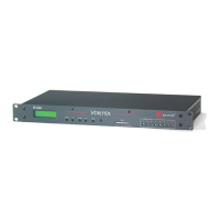
Most of the default parameters of the EF2280 will satisfy our design. However, we will need to
change the Matrix Mixer and Presets to satisfy our design goals.
Matrix Mixer
The matrix mixer will need to be changed from the default settings in order use Output A for the
VSX 8000 and Output B for the Amplifier. Inputs 1-8 need to be assigned to Output A so that the
people on the far end of a VSX 8000 call can hear the local microphones. The cross-points are
colored blue to indicate that they are automixed to Output A.
Inputs C and D are attenuated by 3 dB to Outputs A, B, and R1 to account for a stereo signal being
routed to a mono output. Since the two signals may not be correlated (i.e. have no time
relationship between each other), then when they are added together, the summed signal will be
+3 dB higher.
In this example, we will assume that the VSX 8000, program audio, and amplifier are designed to
send and/or receive a professional level signal. Therefore, Inputs A, C, and D and Outputs A and
B will be set to 0 dB. For more information as to the reasoning behind the gain levels, please see
the Gain Structure for Amplifiers and Other Sources page.
Local Microphones should NEVER be included the reference signal!