'
')XQFWLRQDO'HVFULSWLRQRIWKH&RQWUROOHU
$ SSHQ GL[')XQFWLRQDO'HVFULSWLRQRIWKH&RQ WUROOHU
'2YHUYLHZ
The main function of the controller is to demodulate the radio frequency signal
(RF signal) provided by the interferometer in the sensor head. The frequency
of the signal is the carrier of the velocity information and the phase is the car-
rier of the displacement information. Secondary functions such as human
interfacing, display and filters improve the user friendliness of the vibrometer.
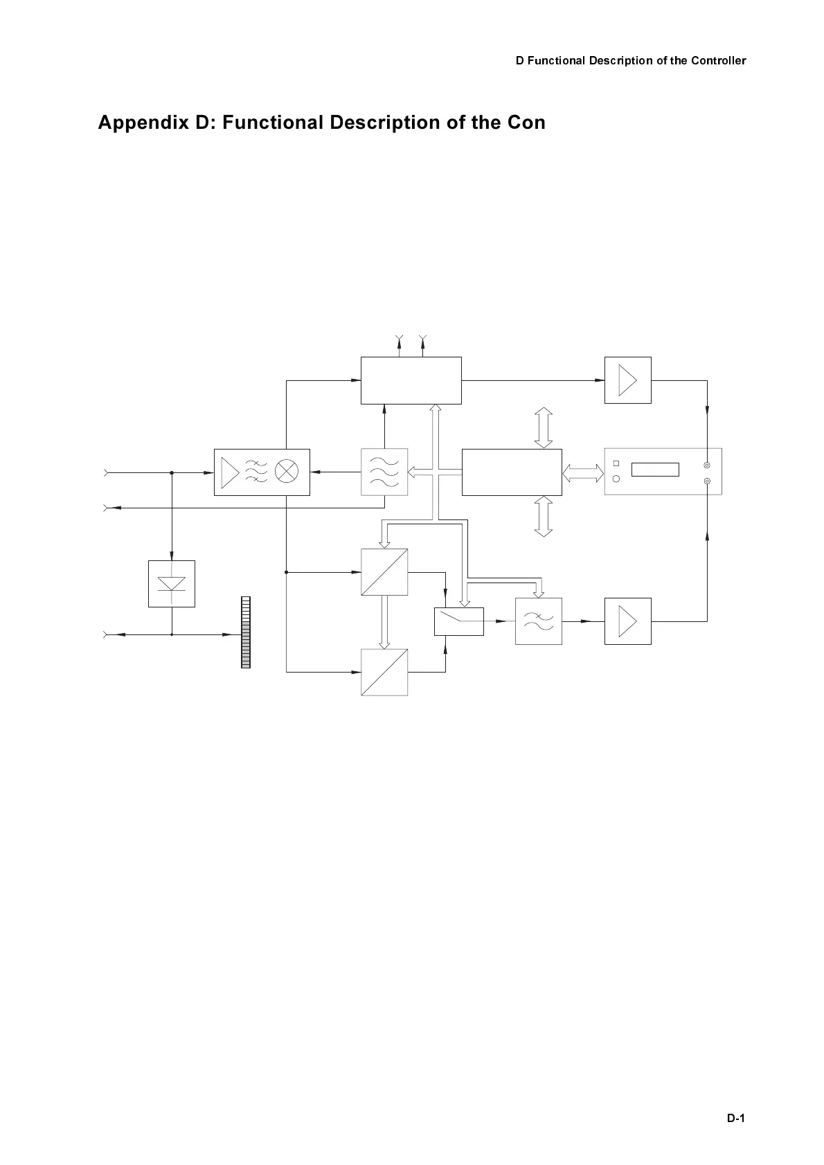
An overview of the functional structure of the controller is shown in figure D.1.
The RF signal from the sensor head (sensor input) initially passes the func-
tional block signal conditioning where it is pre-processed to optimally drive the
following blocks. Subsequently the signal path is split up into the branches
velocity signal decoding (below) and displacement signal decoding (above). If
the controller is fully equipped there are two velocity decoders installed
(demodulator I and demodulator II).
The velocity is modulated on the radio frequency of the input signal. In the
velocity decoder, an AC voltage is generated which is proportional to the
instantaneous velocity of the object with the aid of so-called FM demodula-
tors. In the displacement decoder, optionally the phase of the RF signal is
demodulated. In doing so, an AC voltage is generated which is proportional to
the instantaneous position of the object.
The individual demodulators require different reference frequencies which are
in a fixed relationship to the driver frequency of the Bragg cell in the interfer-
ometer. They are generated in the central oscillator block, synchronized with
the driver signal for the Bragg cell.
Figure D.1: Block diagram of the controller OFV-3001
Signal
C onditioning
O s c illa to r
Level
Detector
Signal
Level
Display
Signal Level
Sensor
Input
Bragg C ell
Drive Out
Output
f
LO
f
B
f
mod
∆
∆
f
V
D em odulator I
∆
f
V
D em odulator II
f
mod
∆
V
mod
V
mod
Switch
C ontrol Bus
Low Pass
A m p lifie r
Velo
Front P anel
Velocity
O utput
System C ontrol
R S -232
IEEE-488
D isplacem ent
D ecoder
(optional)
ϕ
re f
ϕ
mod
PC -based
D isplacem ent D ecoder
Am plifier
Displacement
O utput
Disp