CUSTOM
AIR
CONDITIONING
1A-17
placed Is of great importance. Any attempt to use
COMPRESSOR
REAR
HEAD
ASSEMBLY
makeshift
or inadequate equipment may result In
damage and/or improper operation of compressor.
REMOVE
PRESERVATION
AND
PACKING
SERVICE
PARTS
All
parts required for servicing
will
be protected
by
a preservation
process
and packaged in a manner
which
will
eliminate the necessity of cleaning, wash-
ing
or
flushing
of the parts. The parts can be used
in
the mechanism assembly just as they are re-
moved
from
the service package.
In
addition, some parts
will
be
Identified
on the
piece part to denote its size or dimension. This
will
apply to the piston
shoe
discs and the shaft
thrust
races.
To
provide suitable and
adequate
quantities and
grouping
of parts for servicing the compressor,
kits
are available
which
will
contain
these
neces-
sary parts. The gasket kit should be used whenever
it
is
necessary
to overhaul or
rebuild
entire com-
pressor internal mechanism, or when replacing some
individual
internal part.
OVERHAUL
COMPRESSOR
Anytime
a major overhaul or
rebuilding
opera-
tion
is to be performed on this compressor, obtain
and
install
compressor gasket kit. This kit includes
all
of the
necessary
O-rings and gaskets. Obtain
also, an ample supply of piston rings.
1. Remove compressor oil
plug,
tilt
compressor
and drain oil
Into
clean dry container. It may be
possible to get
only
4 to 6 ozs. of oil
from
the
compressor at this
time.
2.
Attach
J 9396
holding
fixture
to compressor and
mount
in vise.
3.
Remove compressor
pressure
relief
valve.
4.
Remove
four
lock
nuts
from
threaded
studs
welded
to compressor shell and remove rear head.
NOTE:
Some oil may
drain
when the head is
removed.
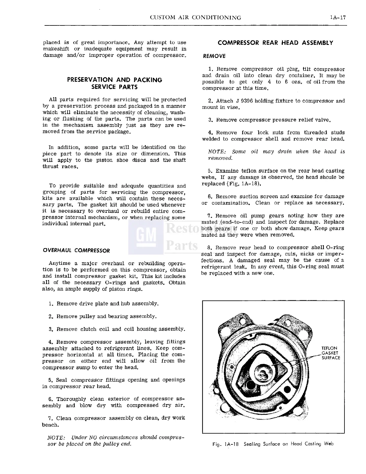
5. Examine
teflon
surface on the rear head casting
webs. If any damage Is observed, the head shoule be
replaced (Fig, 1A-18).
6. Remove suction screen and examine for damage
or
contamination. Clean or replace as
necessary.
7. Remove oil pump
gears
noting how they are
mated (end-to-end) and inspect for damage. Replace
both
gears
if one or both show damage. Keep
gears
mated as they were when removed.
8. Remove rear head to compressor shell
O-ring
seal and inspect for damage, cuts, nicks or imper-
fections.
A damaged seal may be the
cause
of a
refrigerant
leak. In any event, this
O-ring
seal must
be replaced
with
a new one.
1. Remove drive plate and hub assembly.
2.
Remove
pulley
and bearing assembly.
3.
Remove
clutch
coil
and
coil
housing assembly.
4. Remove compressor assembly, leaving
fittings
assembly attached to refrigerant lines. Keep com-
pressor horizontal at all times. Placing the com-
pressor on either end
will
allow
oil
from
the
compressor sump to enter the head.
TEFLON
^GASKET
SURFACE
5. Seal compressor
fittings
opening and openings
in
compressor rear head.
6. Thoroughly clean exterior of compressor as-
sembly
and
blow
dry
with
compressed dry air.
7. Clean compressor assembly on clean, dry
work
bench.
NOTE:
Under NO circumstances should compres-
sor be placed on the
pulley
end.
Fig.
1A-18
Sealing
Surface
on
Head
Casting
Web
 Loading...


