16
Installation
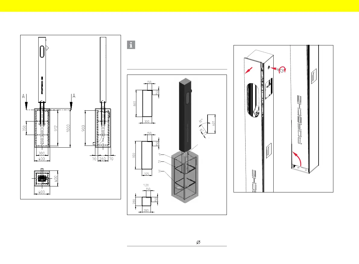
Installation on a substrate/
foundation to be produced on site
Fig. 4: Foundation dimensions
▶ For anchor rod dimensions, see Fig. 2.
Foundation reinforcement diagram
The diagram below shows installation with clearance.
Installation may also be flush with the ground, however.
Fig. 5: Foundation reinforcement diagram
Unlocking the charging pedestal
1. Unlock the front panel with the key.
2. Carefully tilt the front panel forwards and lift up
and out of the base frame.
Fig. 6: Opening the charging pedestal
Information
Structural engineering expertise is required to
produce the foundation in accordance with the
foundation reinforcement diagram.
1 Bracket 1 (2x) 2 Bracket 2 (3x) 3 Bracket 3 (2x)
4 Anchor rod (4x), M12 thread, grade 8.8–10.9
5 Concrete: C 25/30 XF1 XC2
Reinforced concrete: BST 500 S, wire :10 mm